 Dimensions
and drawings of my latest semi-portable coal forge and steel sidedraft
hood.
Dimensions
and drawings of my latest semi-portable coal forge and steel sidedraft
hood.[Home] [Back To The Forge Design] [Blowers, Bellows, Firepots, & Hearths] [Forge Bellows] [Chimneys] [Steel Hoods] [Side Blast Forge Tuyeres] [Tools Racks & Storage] [Styles Of Forges] [Planning Layout of Hearth] [Steel Side-draft Forge and Hood Plans] [Brake Drum Forges] [Costs To Build]
UPDATED September 16th, 2019.
 Dimensions
and drawings of my latest semi-portable coal forge and steel sidedraft
hood.
The hood is made of 14 and 16 gauges sheet metal and 3/16" x 2" x 2" angle iron, and of 1/8" x 1" inch flat stock and a 12" inch square piece of 1/8th inch plate. The bottom of this steel sidedraft hood slopes downward in front, to reach down over the sides of most ready made forges, allowing the front of the hood to come to rest upon the forge hearth beside the firepot. This hood works like a permanently built shop forge with a brick sidedraft chimney. It is of welded construction. Two angle frame members were pre-drilled with a series of mounting height adjustment holes. These pre-drilled frame members were then welded to the rear of the hood frame for attachment to a free standing frame, which supports the weight of the forge and add stability to the hood. The hood can be left standing without a forge beneath it such as for maintenance purposes or while setting up the hood with a forge. The hood weighs roughly 100lbs. The free-standing frame support stand weighs about 60lbs. The idea behind the design of this hood was to build a sidedraft chimney which could be used with just about any ready made shop forge and to be semi-portable.
The chimneys in place are about 3-1/2 feet above the peak of the roof. A bit short of the target of 4 feet but I couldn't reach any higher safely when installing them and used no scaffolding during the setup. After testing the forges again with a good breeze outside, the chimney still draws well. Total length of the chimney is 10-1/2 feet. Photos to follow.
To see more of this forge go to http://www.beautifuliron.com/cf_MySteel.htm. Though this forge isn't quite finished yet, it is in serviceable condition and will be used to make the rest of the parts needed for the final construction of the chimney.
The overall dimensions of the inside of the smoke chamber of this side draft hood are very similar to the internal dimensions of the hoodless stone forge built by Dimitri Gerakaris in the Anvil's Ring March 1979 issue. This hood draws very, very well.
The hood frame is made entirely of angle iron. The top of the frame is square around the hole for the chimney. The angle iron was a little too wide for fitting the flue so, the edges of the angle iron around the flue exit at the top of the hood, had to be trimmed away with a torch allowing the round chimney pipe reinforcement to be attached. The hood was designed to be used with a 12-inch chimney pipe. The reinforcing ring in the top of the hood was a convenient method to attach the chimney pipe and is made just slightly smaller in diameter to fit inside the chimney pipe. The reinforcing ring is made of 3/16" x 1" and welded to the top of the hood.
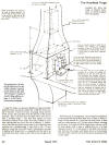
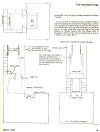 Internal
dimensions of the chimney on this forge are based on Dimitri
Gerakaris's hoodless forges in the Anvil's Ring Vol. 7 #1 from
March 1979. These designs were chosen because they did not smoke like
other chimneys of the previous era. Anyone that has seen an old brick
chimney built during the 1900s is aware that the chimneys during that
era were all smoky. The forges featured in the Anvil's Ring Vol. 7 #1
solved that problem and featured a smoke shelf to help chimney draft
during weather turbulence.
The frame dimensions provided here, show a hood frame that is made from much larger and heavier angle iron than is actually needed. I used whatever steel I had on hand at the time- which was 2" angle iron. The size of the material used in the construction of the hood is not so important. What is important, is the internal dimensions of the chimney. So pay close attention to the internal dimensions of the chimney.
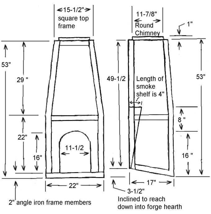 Overall
dimensions. The overall height of this forge is 53". It is 17
inches deep with a smoke entrance 16 inches tall and 11-1/2 inch wide. A
smoke shelf with a length from back wall of inside of hood to the front
edge of the shelf is 4 inches long. The smoke shelf is 8 inches above
the top of the smoke entrance. The bottom surface of the hood angles
down from back to front for a total of 3-1/2 inches to reach down into
the hearth in front of the fire. Not seen in the drawing at right, is
the two pre-drilled angle iron mounting brackets welded to the rear of
the hood frame which allows the hood to be bolted to the stand.
The basic design
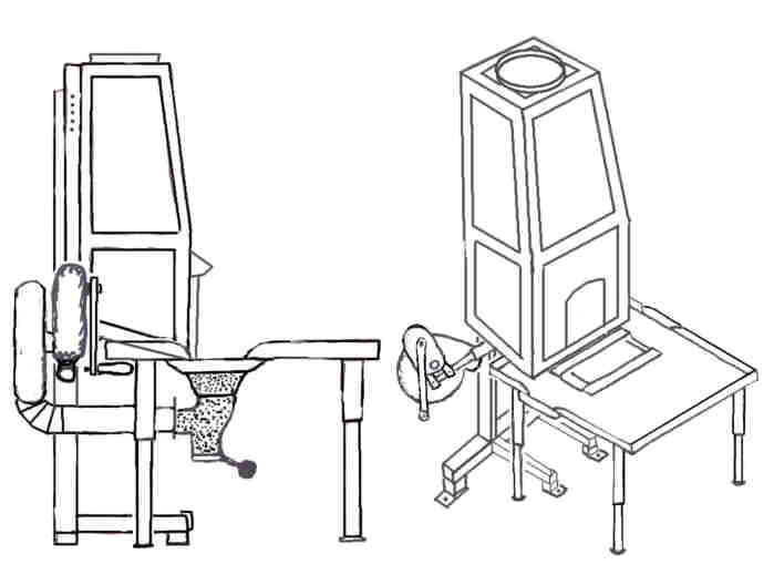
Below is a drawing showing two views of the forge and hood together. The firepot can be seen butted up close to the hood frame. The hood frame slopes down into the forge hearth. A group of holes drilled in the back of the hood frame allows the height of the hood to be adjusted up and down so to allow the hood to reach down into the hearth at the appropriate height. The hood almost completely fills the rear of the forge and the fire builds right up into the front of the smoke entrance of the lower hood. As stated elsewhere, the 2 inch frame of the sidedraft hood is not a hindrance to my fire-building technique as there is normally a group of firebrick surrounding my fires to aid in building a deeper fire. The angle iron frame is of equal or less height than the firebrick normally surrounding my fires.
The blower air delivery pipe reaches around the back of the hood stand frame and passes between the legs of the hood stand frame to enter the tuyere of the firepot.
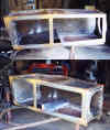 Smoke
shelf. A smoke-shelf made of sheet metal was welded inside the
smoke chamber. Too see how a smoke shelf in a sidedraft chimney
functions go to:
http://www.beautifuliron.com/chimneys.htm. Cutouts were made in the
bottom of the smoke-shelf wall to allow debris to be removed from inside
the smoke shelf. Below are some pictures of the smoke shelf during the
construction of the hood. The smoke shelf in this hood is 4 inches deep.
While my dimensions show an overall dimension of 17 inches outside, it
must be noted that the minimum dimensions inside must be at least 16
inches. There must be a 12 inch space between the front of the smoke
shelf and the front of the inside of the smoke box. The space in front
of the smoke shelf is 22 inches wide. Click on the thumbnailed photo at
left to see large view.
Compatibility of the 2 inch angle iron hood frame. The 2 inch dimension of the angle iron frame is no hindrance to the smoke entrance in the bottom of this hood. The angle iron frame is level with the top of the fire. This means smoke from the fire simply lays over sideways and enters the chimney and need not travel upward at all to do so. The heavier larger size of angle iron aided the construction of the hood and prevented additional warping of the frame as the sheetmetal panels were welded in place.
Choice of square or round chimney flue. Chimneys of square dimension are considered to be equivalent to the same width as a round dimension. The 12 inch round chimney pipe working like a similar 12 inch square masonry chimney flue. The large smoke entrance gets additional draw from a large chimney flue so I recommend at least 12-inch diameter or square flue.
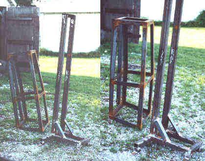 Semi-portable
hood stand. The hood stand can be used with a variety of
different forges built to different heights, including
homemade-fabricated forges and antique factory-made cast iron forges.
Several sets of holes drilled in both the rear frame of the hood and the
two upright posts of the stand, allow easy adjustment of height.
The stand supports the steel hood.
The advantage of building the steel hood stand is to allow the hood to be used free standing and not make the hood dependent on where or how it could otherwise be hung from the wall or ceiling. The forge can be moved elsewhere and the hood will remain standing and ready when the forge is brought back. It also means the hoods can be used where there is no means of hanging from a wall or ceiling in the shop. The stand can be used anywhere and is light enough to be semi-portable (though it is heavy). The selection of bolt holes drilled in the appropriate locations along the length of the rear upright frame members of the stand, allow the hood to be adjusted for use with different forges of different heights.
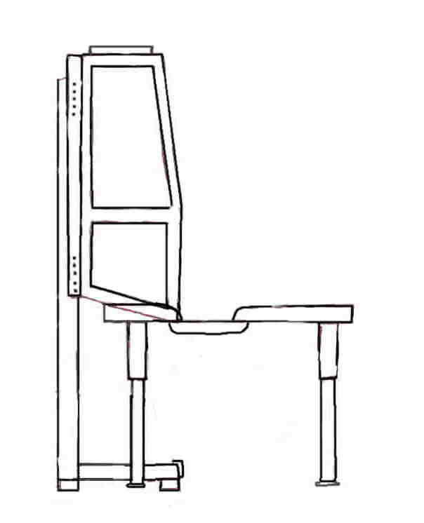
 Hole
scheme allows fine adjustment of hood height above forge.
The holes drilled in the upright posts of the stand are spaced 2" apart for a total linear range of 6". Holes drilled in the rear vertical frame members in the hood frame are spaced 1-1/2" apart which allows the hood to be adjusted in increments of 1/2" at a time. A series of 5 holes total in each group along the rear of the hood frame allow a total linear adjustment 6". The grand total adjustment possibilities are therefore approximately 12" in linear adjustment.
The frame stand is made of two 2" x 4" rectangular tubing with 1/4 wall thickness, 1/4" x 2" x2" angle iron, 1/4" x 2" and 3/16" x 2" angle iron, and 1/4" x 2" inch flat stock. All welded construction. The materials used in this stand were heavier than needed. The 1/4" and 3/16" angle iron were welded alternately back to back to create the square tube frame for the feet and legs. The 1/4" x 2" flat steel was used for gussets and other pieces as needed. Lighter weight materials such as 1/8" wall/thickness rectangular tubing would probably work just as well for the upright posts and would be much lighter.
The stand is much more stable then I first expected and it will support the hood by itself. However bolt holes have been drilled in the feet to allow the stand to be secured to the floor.
 The
forge plan
The hearth was cut out of my old brick and steel forge. The hearth is 31-1/2" above the floor, 36" long, and 32" wide. The firepot is about 7-1/2" from the rear of the forge to the rear edge of the firepot. The firepot is therefore about 14-1/2" from the front of the hearth to the front edge of the firepot.
Lateral distance between blower crank and hearth is important!
A blower handle too close to the hearth will cause the handle to foul long work which extends past the edge of the hearth. It would be even more embarrassing to position a blower so that that hand crank can't even be turned without fouling the hearth itself! In the case of this forge, the blower crank is about 9" long from center of handle grip to the center of the gear shaft. The lateral distance (horizontal distance) between the edge of the hearth to the center of the crank gear shaft, is about 12-1/2" to 13" roughly. The blower is mounted at a height that insures the smith need not bend over to grip the crank handle while rotating the handle around its entire circular path.
Height is important. Though we don't want to reach too high up to rotate a blower crank handle, it is just as bad to reach too low when cranking the blower. We mount the blower at a height that allows the smith to stand straight and tall while grasping the blower handle in its lowest position of travel. In the case of the forge pictured below, this height means that lowest position of the handle is no more than 1/2 inch below the level of the forge hearth. This doesn't mean that all everyone should place their blowers so the handle is 1/2" below the hearth. It simply means that on this forge the handle happens to come to that height. Again, mount the blower so that the smith may grasp it without bending while the handle is in its lowest position of travel.
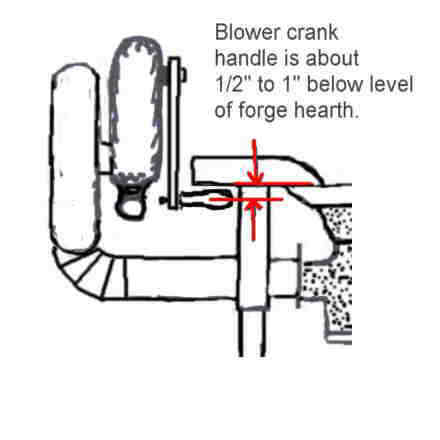
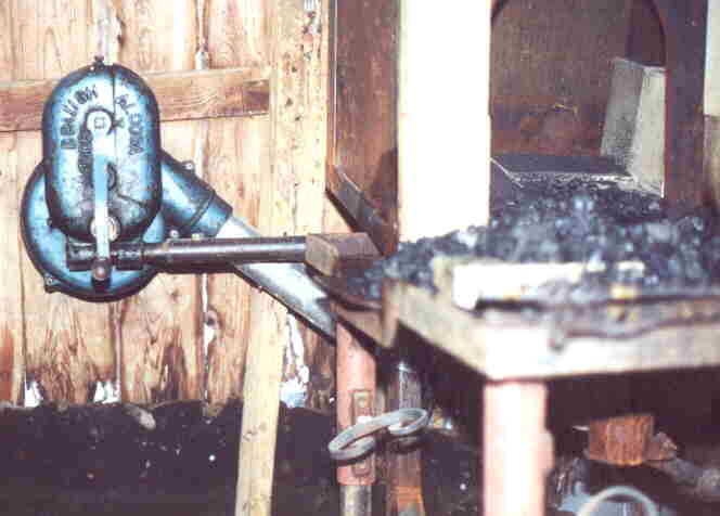
Placement of blower
 Here
are some photos which show the blower mounted to the forge. The end of
the handle is placed evenly with the rear edge of the forge hearth which
places it about 7 inches to the rear of the firepot. It is important to
note here that the smith who must heat long bars will also need room to
stand between the iron being heated, and the crank handle of the blower.
Many factory made forges do not provide enough room between the blower
crank and the area where long bars are placed for heating. In that
latter case the smith is forced to stand on the opposite side of the
blower or in another awkward position in order to crank the blower to
heat long bars. The larger distances we can design into our modern
shop-built forges between the blower crank handle and firepot, can
accommodate this need and allow the smith to work more comfortably. In
this case about 7 inches provide a narrow but useable area to work. This
forge is too small to accommodate a larger distance/placement and remain
stable during setup. My old steel and brick forge seen at
http://www.beautifuliron.com/cf_BrickAndSteel.htm used a much greater distance
between blower crank and fire but this wasn't feasible on this forge due
to light weight and balance of forge hearth.
Height of blower handle.
While the blower handle on this forge is seen slightly below the
level of the forge hearth here, this distance is only by coincidence and
is not important. I gave that distance for comparison only. The actual
height I use for my blowers allows the handle in its lowest position of
travel, to be about 32 inches measured from the floor of the shop. This
height represents the relationship of my height and length of my arms.
Each smith will need to measure themselves for this crank height and
apply this measurement to their own forge design. Look at the photo at
the bottom of this page. While the forge in this last photo is a
factory-made forge, the height of the blower crank handle almost
identical.
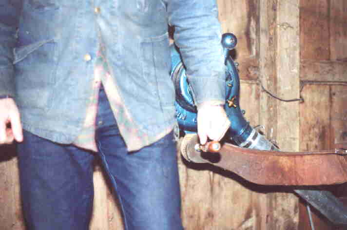
How to measure height for placement of blower.
Mistake in photo at right! Standing straight and tall, arms straight down at sides but not rigid, and grasp the blower handle. The handle should fill the smiths hand with the arms straight down at the smith's sides. This is where the center of crank handle of blower should be placed and this measurement is designed into the fabrication of the forge.
In the photo example above right the handle is just a little bit low. The second finger joint of the smith's hand comes to rest on top of the handle grip. The forge at right is a cast iron manufactured forge so the only way to solve the height problem is to place blocks under the legs of the forge to lift it a bit. The hearth is just a bit low also so raising the height of this forge will be a benefit anyway.
Latest Update December 21st, 2001.
Begun September 23, 2000. Under construction.
This page currently being updated. Please check back later as the latest updates are finalized.
The author can be emailed at address in picture below: