 Hand-powered
drill press
Hand-powered
drill press[Home] [Back to Ye Old Drill] [Camelback Drills] [Morse Taper] [Standard No. 2 Chuck] [Westcott's Little Giant Chuck] [Jacobs Chucks] [The Post Drill] [Restoring Canedy-Otto No. 16]
Hand-powered
drill press
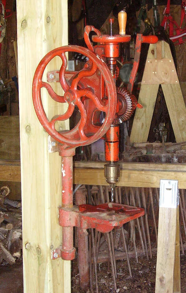
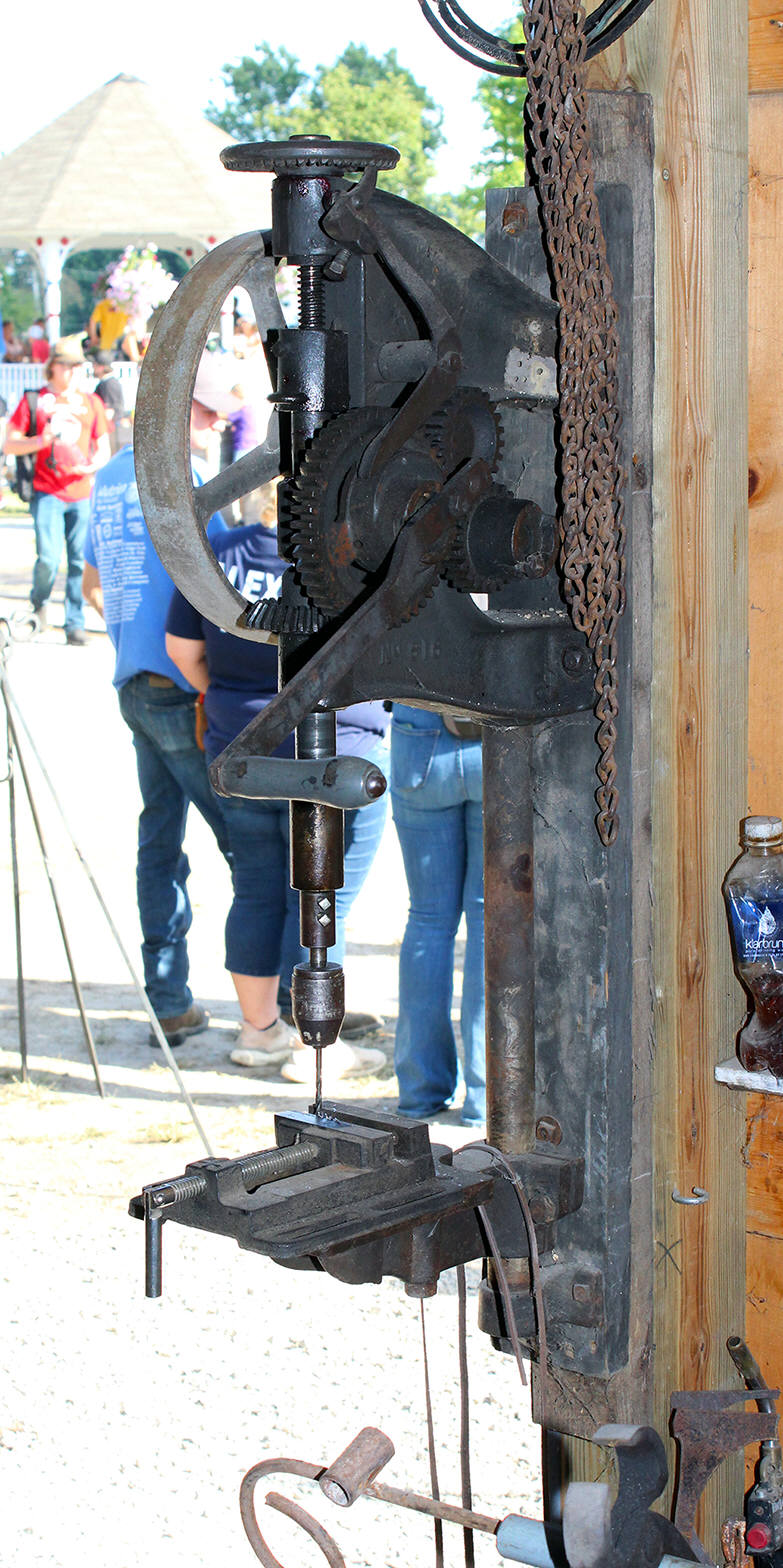
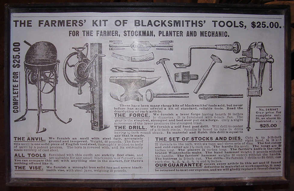
How did farmers and mechanics perform drilling tasks on iron and steel during the early industrial era - before electrical power was common in every home and business? They used a hand-cranked drill press like the post drills shown on this page. No electric motor, no belt power, the drill is hand powered by turning the hand crank. The post drill is supplied with a self-feed mechanism that automatically advances the drill bit into the work while the drill is turning. The user simply holds the work piece on the drill table with one hand while turning the hand crank with the other hand. The drill bit is automatically forced/fed downward into the work by a reciprocating/ratcheting wheel and screw mechanism while the drill was turning.
The post drill is a small hand-powered drill press capable of drilling anything that can be drilled by a modern line-shaft or electric motor powered drill press of equivalent size. Post drills were small (compared with the large line-shaft driven camelback drill presses) and easily crated and shipped to any location.
Useful and reliable relic from the past. Today the post drill has been almost entirely forgotten, an archaic antique of unknown purpose, treasured only by tool collectors and craftsmen who enjoy the atmosphere that these old tools give. However if electrical power is unavailable (whether by emergency or as part of routine construction work), these old drills continue to offer the ability to get small drilling jobs done, albeit with plenty more effort than a modern electric drill press. The post drill is an excellent choice for small wood working shops and small blacksmith shops that don't have access to electricity, and it is a 'must' have machine for farms that need to make repairs after storms have knocked out electrical service. And no, a battery-powered drill isn't a viable subsititute for a drill press. The post drill is in fact, a drill press, and will handle larger holes and deeper drilling than a battery powered drill, and needs no batteries or electricity to charge. Try drilling a half dozen 5/8ths inch or larger holes through a 1/2 steel plate. How many batteries will the battery powered drill need? Will the battery powered drill motor burn up before all 6 holes are finished?
 The post drill is an excellent tool for drilling jobs on small construction
sites where electrical power is intentionally turned off and a good strong drill
press type of drill is needed for a small number of drilling tasks. For
emergency repairs, the post drill runs even after electrical power is knocked
out by storms. Small and medium sized post drills are light enough to be
transported to remote job sites (in the back of a pickup truck, trailer, or
wagon) when a drill press is needed but no electrical power available. Large
post drills weigh as much as 450#s and require at least two men to move. Large
post drills are desinged for much larger and heavier drilling and are best
used in shops where they can be powered by line shaft belts or electric motors.
The post drill is an excellent tool for drilling jobs on small construction
sites where electrical power is intentionally turned off and a good strong drill
press type of drill is needed for a small number of drilling tasks. For
emergency repairs, the post drill runs even after electrical power is knocked
out by storms. Small and medium sized post drills are light enough to be
transported to remote job sites (in the back of a pickup truck, trailer, or
wagon) when a drill press is needed but no electrical power available. Large
post drills weigh as much as 450#s and require at least two men to move. Large
post drills are desinged for much larger and heavier drilling and are best
used in shops where they can be powered by line shaft belts or electric motors.
Latest update March 15, 2023. Biggest update in literally years has now been added to this page. Reformatted the Gallery of Drills (further down this page) and added high quality photos of two additional models of post drills. Planning to finally add drawings and dimensions for free standing post drill stands (small photo at right) later this winter after shop renovation is complete for the year. These free standing post drill mounts allow the post drills (the red drill (photo at top left of this page) and the Champion No. 98 further down this page) to be used anywhere in the shop and allows them to be moved around the shop like any small modern drill press.
Antique post drill -vs.- the modern drill press. Drilling with a post drill will proceed more slowly and with more difficulty because the mechanic must supply the necessary hand power to turn the drill. Motor-driven drill presses will drill faster and are far less fatiguing to operate compared to a hand-cranked drill. Post drills operate without electricity, modern drill presses require electrical power.
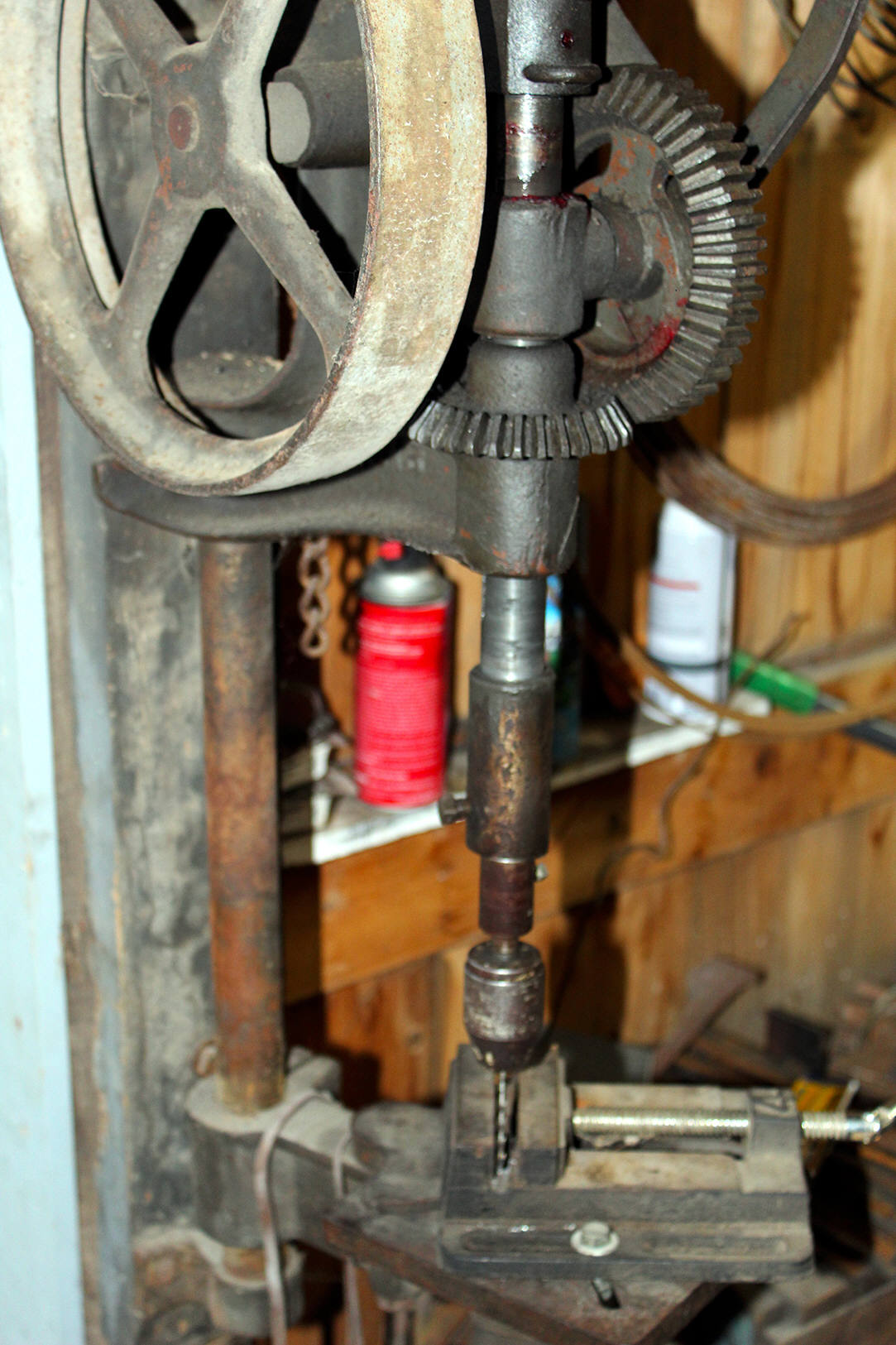
About the red post drill shown in this article: This drill (unknown manufacture) is owned by the author (me). It was purchased for $55 at a draft horse auction in Kalona, Iowa, USA, around 1998. The drill was in perfect/new condition and included a modern Jacobs #3B drill chuck with a homemade arbor that was fitted in the original antique screw chuck. The Jacobs chuck that was installed on this drill allows the use of modern (round shank) drill bits. See the photo at left.
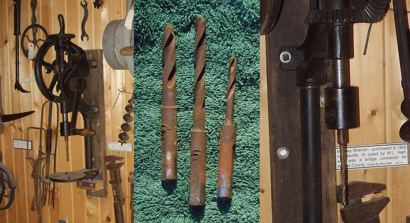 Straight
shank drill bits. Special drill bits, called 'straight shank' bits, were made
specifically for post drills. These drill bits were made in many sizes, but all
had common shank sizes including 1/2-inch diameter, 5/8-inch diameter, and
41/64-inch diameter. Straight shank drill bits were round in cross section with a
flat machined on one side of the shank. The straight shank drill bit was never
truly centered in the drill chuck (due to the required manufacturing tolerances
between the drill shanks and the chucks) and therefore some drill wobble or runout
was always to be expected. These drills were made for simple manufacturing and
repairs in farm shops and small home workshops, where a great amount of accuracy
was not necessary. Three antique straight shank drill bits are shown in the
photo (at right). Look closely at the drills in this photo; the drills are of
different sizes but the shanks are all the same size. The drill bits shown here
belong to a friend of the author.
Straight
shank drill bits. Special drill bits, called 'straight shank' bits, were made
specifically for post drills. These drill bits were made in many sizes, but all
had common shank sizes including 1/2-inch diameter, 5/8-inch diameter, and
41/64-inch diameter. Straight shank drill bits were round in cross section with a
flat machined on one side of the shank. The straight shank drill bit was never
truly centered in the drill chuck (due to the required manufacturing tolerances
between the drill shanks and the chucks) and therefore some drill wobble or runout
was always to be expected. These drills were made for simple manufacturing and
repairs in farm shops and small home workshops, where a great amount of accuracy
was not necessary. Three antique straight shank drill bits are shown in the
photo (at right). Look closely at the drills in this photo; the drills are of
different sizes but the shanks are all the same size. The drill bits shown here
belong to a friend of the author.
Drilling capacity of post drills. Manufacturers advertisements and catalogs often state the maximum size of hole that can be drilled with each model of post drill. As an example, the red post drill shown at top of this page, is rated for drilling holes up to 1-inch in diameter. These drilled hole size ratings are correct but, due to the hand-powered nature of the post drill, maximum hole drilling capacity will actually depend on the physical strength and stamina of the user.
First we begin with the old style chucks that were originally installed on these drills by the manufacturer, then we move on to setting up and installing modern adjustable drill chucks.
Three different original style post drill chucks are shown here below - simple screw chuck, the Champion Blower & Forge 'Never-Slip Drill Chuck', and the Canedy-Otto 'Western Chief Safety Chuck'.
Early post drill chucks, and some of the later cheaper models of post drills, had drill bit set screws portruding out of the side of the chuck body. These set screws presented a hazard as they could tear at clothing or nip at the user's hands or arms while working with the drill. Later models of post drill were equipped with drill chucks that featured recessed set screw holes so as to not present protrusions that might injure the workman while the drills are turning. Antique post drill chucks can be quickly updated to accept modern drill chucks by first installing a small straight shank chuck arbor into a modern drill chuck.
Original chucks supplied with the drill
 Simple
screw chuck. The red post drill shown here (photo at right and photo at
top of page) was
provided with a simple screw chuck. The screw chuck resembles a small hollow
barrel with two holes bored in one side, and a set screw threaded into
the lower hole. The chuck is threaded onto the drill spindle. The upper hole
appears to be a spanner wrench hole - to allow the use of a spanner wrench to
install the chuck on the drill spindle. The lower hole was threaded and
countersunk to allow the set screw to fit completely inside the body of the
chuck - thus presenting no protrusions that could cause injury to the workman
while the drill was turning. The drill bit was inserted in the socket of the
chuck and rotated slightly to insure that the set screw was pressing against the
flat of the drill shank. The set screw is then tightened against the flat of the
drill bit shank to hold the drill bit in place and to prevent the bit from
slipping during drilling. A small wrench was supplied with the chuck for
tightening the set screw onto the drill bits. Post drill chucks were manufactured
in 3 common sizes: 1/2-inch, 5/8-inch, and 41/64-inch. This was one of
the most common chucks found on many post drills.
Simple
screw chuck. The red post drill shown here (photo at right and photo at
top of page) was
provided with a simple screw chuck. The screw chuck resembles a small hollow
barrel with two holes bored in one side, and a set screw threaded into
the lower hole. The chuck is threaded onto the drill spindle. The upper hole
appears to be a spanner wrench hole - to allow the use of a spanner wrench to
install the chuck on the drill spindle. The lower hole was threaded and
countersunk to allow the set screw to fit completely inside the body of the
chuck - thus presenting no protrusions that could cause injury to the workman
while the drill was turning. The drill bit was inserted in the socket of the
chuck and rotated slightly to insure that the set screw was pressing against the
flat of the drill shank. The set screw is then tightened against the flat of the
drill bit shank to hold the drill bit in place and to prevent the bit from
slipping during drilling. A small wrench was supplied with the chuck for
tightening the set screw onto the drill bits. Post drill chucks were manufactured
in 3 common sizes: 1/2-inch, 5/8-inch, and 41/64-inch. This was one of
the most common chucks found on many post drills.
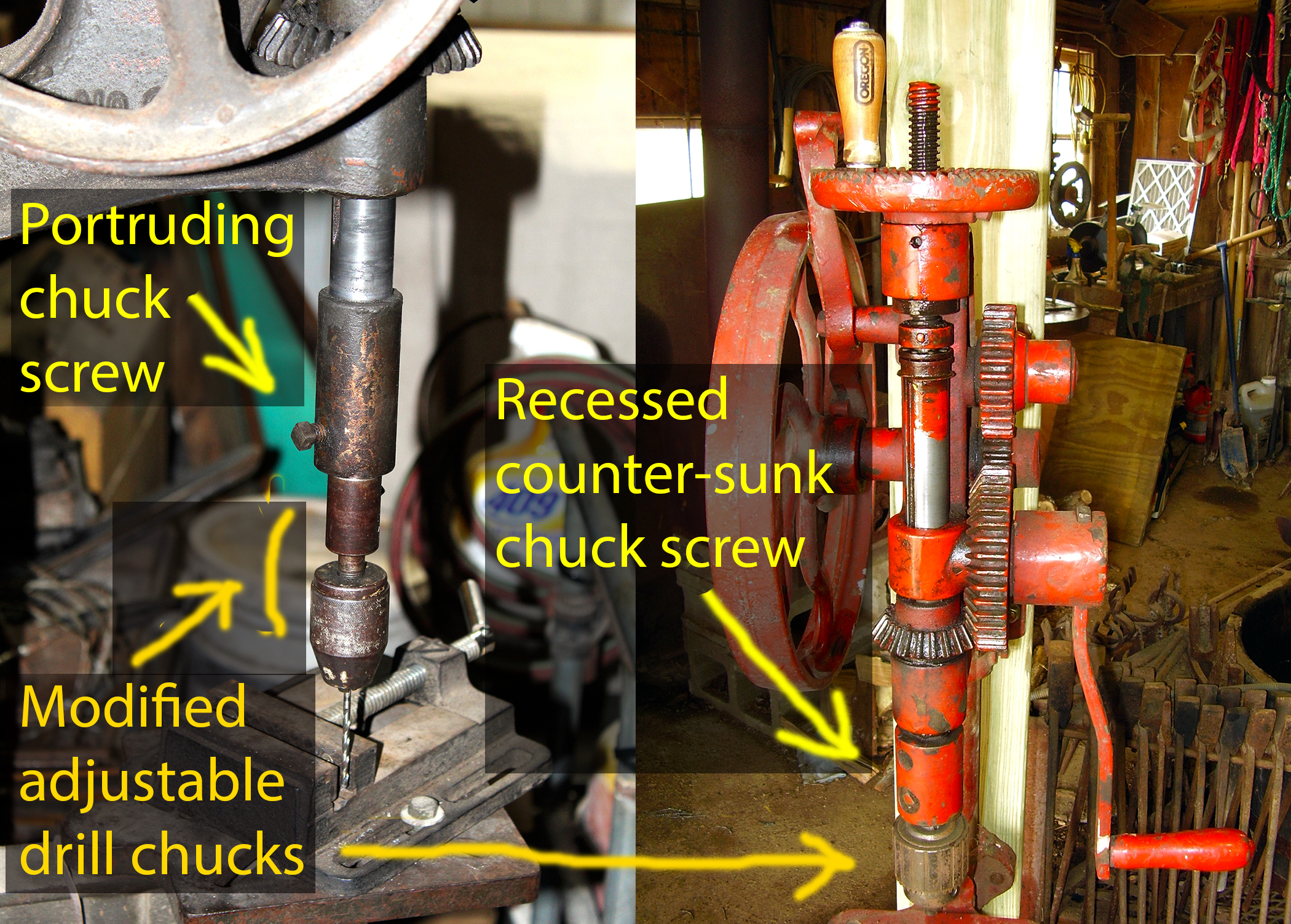 NOTE:
During the late 1800's, industry began
taking action to improve safety while working with machine tools. The first
safety features used on drills, was to reduce the dangers of injury while
working in close proximity with sharp spinning objects. The original chuck set
screws protruded outside the profile of the chuck - presenting a risk of injury
to the mechanic's hands when the drill was spinning. One of the earliest safety designs
resulted in building a thicker chuck that allowed for creation of a recessed set
screw. The recessed set screw insured that the sharp edged profile of the set
screw was located entirely inside the body of the drill chuck - thus presenting
no sharp protrusions that might otherwise snag at the workman's clothing or body
as the drill was spinning. See the composite photo at right for an
example of recessed and non-recessed set screw chucks. Early manufactured post
drills and many of the cheaper-priced post drills will have set screws protruding
outside of the body of the chuck because a recess for the set screw was
never machined on older or cheaper drill chucks. Beware that a spinning chuck set screw
can snag clothing or gloves and cause injury.
NOTE:
During the late 1800's, industry began
taking action to improve safety while working with machine tools. The first
safety features used on drills, was to reduce the dangers of injury while
working in close proximity with sharp spinning objects. The original chuck set
screws protruded outside the profile of the chuck - presenting a risk of injury
to the mechanic's hands when the drill was spinning. One of the earliest safety designs
resulted in building a thicker chuck that allowed for creation of a recessed set
screw. The recessed set screw insured that the sharp edged profile of the set
screw was located entirely inside the body of the drill chuck - thus presenting
no sharp protrusions that might otherwise snag at the workman's clothing or body
as the drill was spinning. See the composite photo at right for an
example of recessed and non-recessed set screw chucks. Early manufactured post
drills and many of the cheaper-priced post drills will have set screws protruding
outside of the body of the chuck because a recess for the set screw was
never machined on older or cheaper drill chucks. Beware that a spinning chuck set screw
can snag clothing or gloves and cause injury.
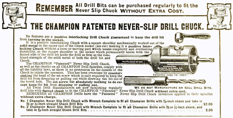 Champion Never-Slip Chuck looks similar to the screw chuck described
above but, take a closer look, an important feature makes this chuck superior to
the screw chuck. What makes the Never-Slip Chuck different from a typical
screw chuck is, the shape or profile of the drill bit socket inside the chuck.
The drill bit socket is not round, it is instead shaped like the shank of the
straight shank drill bit (round, with a flat land), thus providing a solid
physical interlock that prevents the drill bit from slipping. The set screw
therefore is only needed to prevent the drill bit from pulling out of the
chuck while being raised up out of the work. A small wrench was supplied with
the chuck for tightening the set screw onto the drill bits. On the outside,
the Champion Never-Slip Chuck looks identical to a screw chuck - a small
hollow barrel with two holes bored in one side, and a set screw threaded into
the lower hole. The Never-Slip Chuck is threaded onto the drill spindle, and
the hole in the upper section of the screw chuck appears to be a spanner
wrench hole - to allow the use of a spanner wrench to install the chuck on the
drill spindle. The lower hole was threaded and countersunk to allow the set
screw to fit completely inside the body of the chuck - thus presenting no
protrusions that could cause injury to the workman while the drill was
turning.
Champion Never-Slip Chuck looks similar to the screw chuck described
above but, take a closer look, an important feature makes this chuck superior to
the screw chuck. What makes the Never-Slip Chuck different from a typical
screw chuck is, the shape or profile of the drill bit socket inside the chuck.
The drill bit socket is not round, it is instead shaped like the shank of the
straight shank drill bit (round, with a flat land), thus providing a solid
physical interlock that prevents the drill bit from slipping. The set screw
therefore is only needed to prevent the drill bit from pulling out of the
chuck while being raised up out of the work. A small wrench was supplied with
the chuck for tightening the set screw onto the drill bits. On the outside,
the Champion Never-Slip Chuck looks identical to a screw chuck - a small
hollow barrel with two holes bored in one side, and a set screw threaded into
the lower hole. The Never-Slip Chuck is threaded onto the drill spindle, and
the hole in the upper section of the screw chuck appears to be a spanner
wrench hole - to allow the use of a spanner wrench to install the chuck on the
drill spindle. The lower hole was threaded and countersunk to allow the set
screw to fit completely inside the body of the chuck - thus presenting no
protrusions that could cause injury to the workman while the drill was
turning.
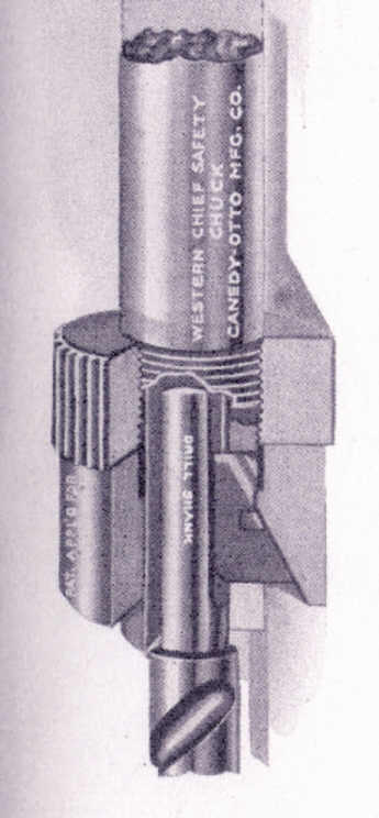
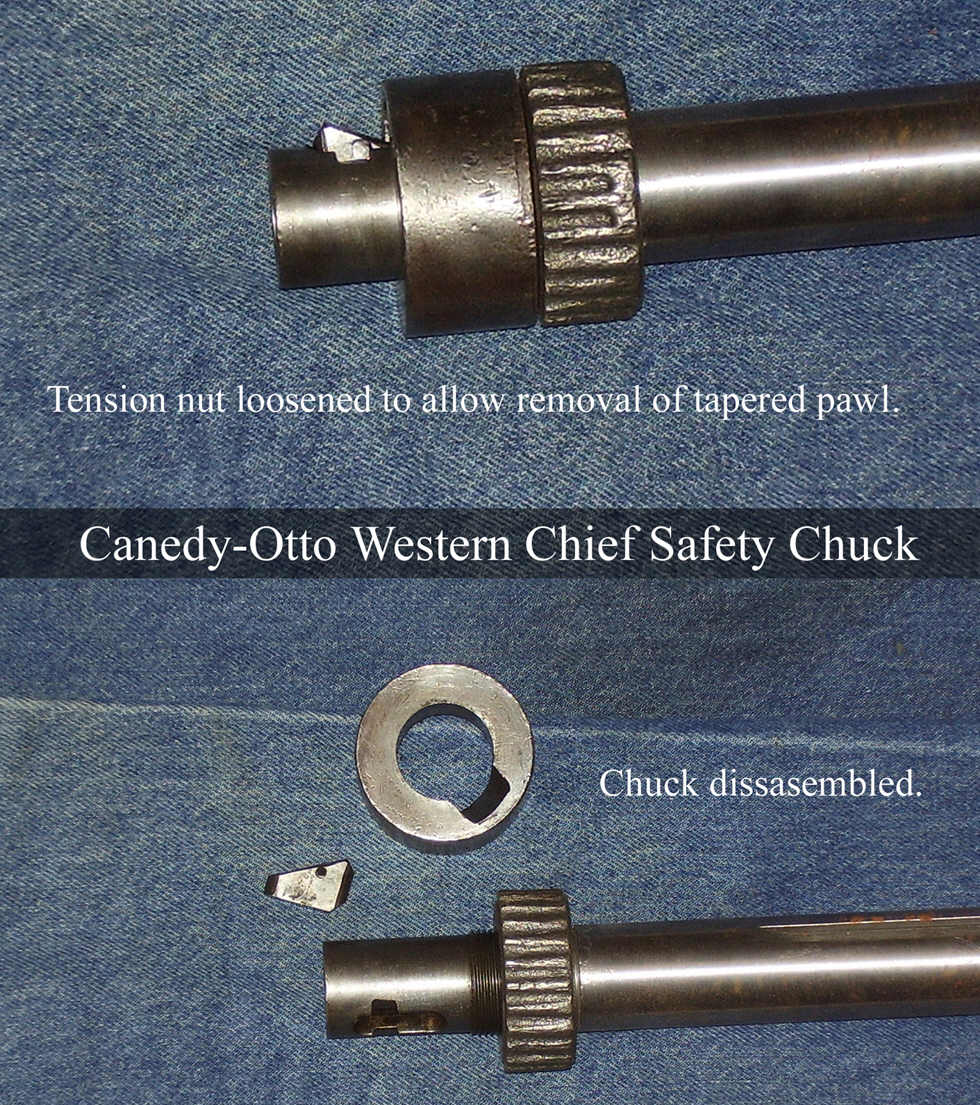
 Canedy-Otto 'Western Chief Safety Chuck' is a wedge and sleeve design.
The flat surface of the wedge clamps tightly against the flat of the straight
shank drill bit inside the Safety Chuck. The lower sleeve of the chuck has a
tapered slot that presses against the inclined surface of the wedge - forcing
the wedge inward against the drill bit as the threaded ferrule is tightened
against the sleeve. Tightening the wedge against the flat of the drill bit
provides the non-slip interlock that holds the drill bit tightly in the chuck.
The Western Chief Safety Chuck needs no set screws or wrenches. The Safety Chuck
socket and wedge slot were machined directly into the end of the drill spindle.
Safety Chucks were also available as a separate product with a straight shank
arbor to fit in the socket of another chuck, this being necessary when drill bit
shanks were not of the same size as the chuck that was originally installed on
the post drill. The wedge and sleeve design was vastly superior to the screw
chuck in that, it provided a very strong non-slip grip on the straight shank
drill bit, and the wedge and sleeve design did not cause any gouging or galling
of the drill bit that was typically caused by a set screw. The Canedy-Otto was
tightened by hand - gripping the knurled ferrule and twisting it to tighten the
wedge against the drill bit until it is hand tight. In the photos at right, a
Canedy-Otto Western Chief Safety Chuck is shown with a taper shank extension
that has been modified to fit in the 41/64-inch chuck. The taper shank extension
in this photo is used as an adapter to accept taper shank drill bits without
modifying the drill. The photo at middle right shows the Western Chief Safety
Chuck disassembled, and the photo at far right shows a cut-away drawing of the
inside of the Canedy-Otto Western Chief Safety Chuck.
Canedy-Otto 'Western Chief Safety Chuck' is a wedge and sleeve design.
The flat surface of the wedge clamps tightly against the flat of the straight
shank drill bit inside the Safety Chuck. The lower sleeve of the chuck has a
tapered slot that presses against the inclined surface of the wedge - forcing
the wedge inward against the drill bit as the threaded ferrule is tightened
against the sleeve. Tightening the wedge against the flat of the drill bit
provides the non-slip interlock that holds the drill bit tightly in the chuck.
The Western Chief Safety Chuck needs no set screws or wrenches. The Safety Chuck
socket and wedge slot were machined directly into the end of the drill spindle.
Safety Chucks were also available as a separate product with a straight shank
arbor to fit in the socket of another chuck, this being necessary when drill bit
shanks were not of the same size as the chuck that was originally installed on
the post drill. The wedge and sleeve design was vastly superior to the screw
chuck in that, it provided a very strong non-slip grip on the straight shank
drill bit, and the wedge and sleeve design did not cause any gouging or galling
of the drill bit that was typically caused by a set screw. The Canedy-Otto was
tightened by hand - gripping the knurled ferrule and twisting it to tighten the
wedge against the drill bit until it is hand tight. In the photos at right, a
Canedy-Otto Western Chief Safety Chuck is shown with a taper shank extension
that has been modified to fit in the 41/64-inch chuck. The taper shank extension
in this photo is used as an adapter to accept taper shank drill bits without
modifying the drill. The photo at middle right shows the Western Chief Safety
Chuck disassembled, and the photo at far right shows a cut-away drawing of the
inside of the Canedy-Otto Western Chief Safety Chuck.

 Converting the antique post drill for modern drill bits.
Post drills were made during an era when common size straight shank drill bits
were widely available. These old 'blacksmith' drill bits are no longer
manufactured. Placing a modern drill chuck in the original antique chuck allows
the post drill to accept modern drill bits without requiring any permanent
changes to the drill or chuck. The only part that requires modification is the
arbor of the new drill chuck. An example of this is the Jacobs #3B 1/2-inch
drill chuck installed on the red post drill in the photos (at right). The round
shank of a new chuck arbor should be trimmed to length and machined with a flat
similar to the shank of a straight shank drill bit. The flat should be milled
onto the shank, it can be machined into the shank by grinding but beware - heat
from grinding could warp the shank and cause the drill to wobble or 'run-out'
excessively during use. Arbor shank length should be short as possible to reduce
run-out or wobble.
Converting the antique post drill for modern drill bits.
Post drills were made during an era when common size straight shank drill bits
were widely available. These old 'blacksmith' drill bits are no longer
manufactured. Placing a modern drill chuck in the original antique chuck allows
the post drill to accept modern drill bits without requiring any permanent
changes to the drill or chuck. The only part that requires modification is the
arbor of the new drill chuck. An example of this is the Jacobs #3B 1/2-inch
drill chuck installed on the red post drill in the photos (at right). The round
shank of a new chuck arbor should be trimmed to length and machined with a flat
similar to the shank of a straight shank drill bit. The flat should be milled
onto the shank, it can be machined into the shank by grinding but beware - heat
from grinding could warp the shank and cause the drill to wobble or 'run-out'
excessively during use. Arbor shank length should be short as possible to reduce
run-out or wobble.
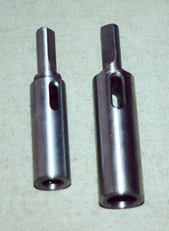
 Morse
taper socket extensions (photo at far right) can also be modified to fit in a
post drill to allow taper shank drill bits to
be used. This is done by machining the 3MT shank on the extension
to reduce the shank to 5/8-inch straight shank, trimming the excess length and
machining a flat on the shank. Extensions are available in a variety of sizes.
This author converted two socket extensions to allow 2MT and 3 MT drill bits to
be used with the socket extension in the post drill. (See photo at far right.)
To save money on purchasing and machining extensions, buy one extension (3MT to 3MT)
and two sleeves (one 3MT to 2MT) and (one 3MT to 1MT). This allows smaller 2MT and 1MT shank drill bits to be used
in the same socket extension with a 3MT socket. Sleeves (photo near right) owned
by the author.
Morse
taper socket extensions (photo at far right) can also be modified to fit in a
post drill to allow taper shank drill bits to
be used. This is done by machining the 3MT shank on the extension
to reduce the shank to 5/8-inch straight shank, trimming the excess length and
machining a flat on the shank. Extensions are available in a variety of sizes.
This author converted two socket extensions to allow 2MT and 3 MT drill bits to
be used with the socket extension in the post drill. (See photo at far right.)
To save money on purchasing and machining extensions, buy one extension (3MT to 3MT)
and two sleeves (one 3MT to 2MT) and (one 3MT to 1MT). This allows smaller 2MT and 1MT shank drill bits to be used
in the same socket extension with a 3MT socket. Sleeves (photo near right) owned
by the author.
Post drills require good quality drill chucks. Post drills are very tough drilling machines and they place a large amount of stress and torque on drill bits and chucks. The original straight shank bits had a flat groove machined on the side of the shank that allowed a positive (non-slip) grip on the drill bit, and this flat groove allowed the drill to turn forcefully in the work. A typical modern drill bit does not have a machined groove on the side of the shank, and consequently a modern drill chuck must rely on friction to hold the bit during heavy drilling. Therefore it is important to choose a drill chuck that can hold a drill bit very tightly. It is best to use Jacobs brand or equivalent heavy duty drill chucks. Cheap imported chucks often 'pop' open during heavy drilling.
 Where
can I buy new chuck arbors? This author recommends
MSC Industrial and
McMaster-Carr. MSC Industrial Supply website:
http://www.mscdirect.com
McMaster-Carr website: http://www.mcmaster.com
These links also appear on my
Links page under the heading Machine Shop Tooling & Supplies. There are only
two sizes of straight shank arbors available, and these are 1/2-inch round and
5/8-inch round. The 5/8-inch round is used in place of 41/64-inch size. It
is important to understand exactly how arbors are sized before ordering new.
Drill chuck arbors are machined in a large number of size combinations to mount
any chuck onto any drill. Chucks are fitted onto the arbor with either a Jacobs
taper or threaded end. Morse taper or straight shank ends fit into the press
spindle socket. Straight shank (both 1/2-inch and 5/8-inch) arbors are available
for most Jacobs taper sizes and threaded sizes.
Where
can I buy new chuck arbors? This author recommends
MSC Industrial and
McMaster-Carr. MSC Industrial Supply website:
http://www.mscdirect.com
McMaster-Carr website: http://www.mcmaster.com
These links also appear on my
Links page under the heading Machine Shop Tooling & Supplies. There are only
two sizes of straight shank arbors available, and these are 1/2-inch round and
5/8-inch round. The 5/8-inch round is used in place of 41/64-inch size. It
is important to understand exactly how arbors are sized before ordering new.
Drill chuck arbors are machined in a large number of size combinations to mount
any chuck onto any drill. Chucks are fitted onto the arbor with either a Jacobs
taper or threaded end. Morse taper or straight shank ends fit into the press
spindle socket. Straight shank (both 1/2-inch and 5/8-inch) arbors are available
for most Jacobs taper sizes and threaded sizes.
New arbors will require machining (as described in the first paragraph in this section above 'Converting the antique post drill for modern drill bits'). New arbors can be purchased for around $15-19 (prices around 2008-2009) and machined to fit the post drill for about $40 (2008-2009 machining prices).
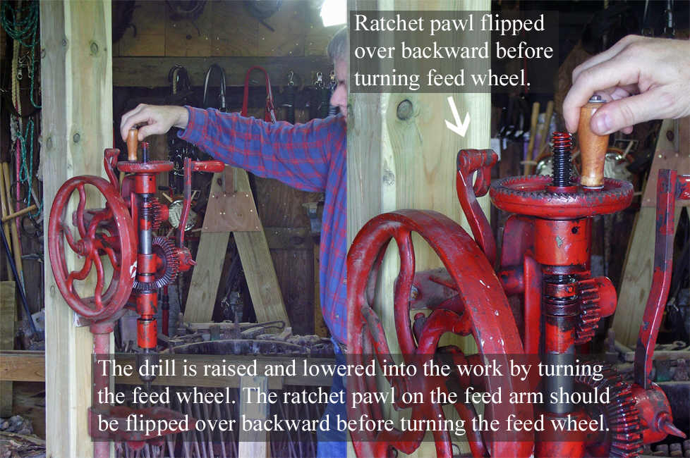
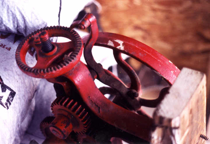
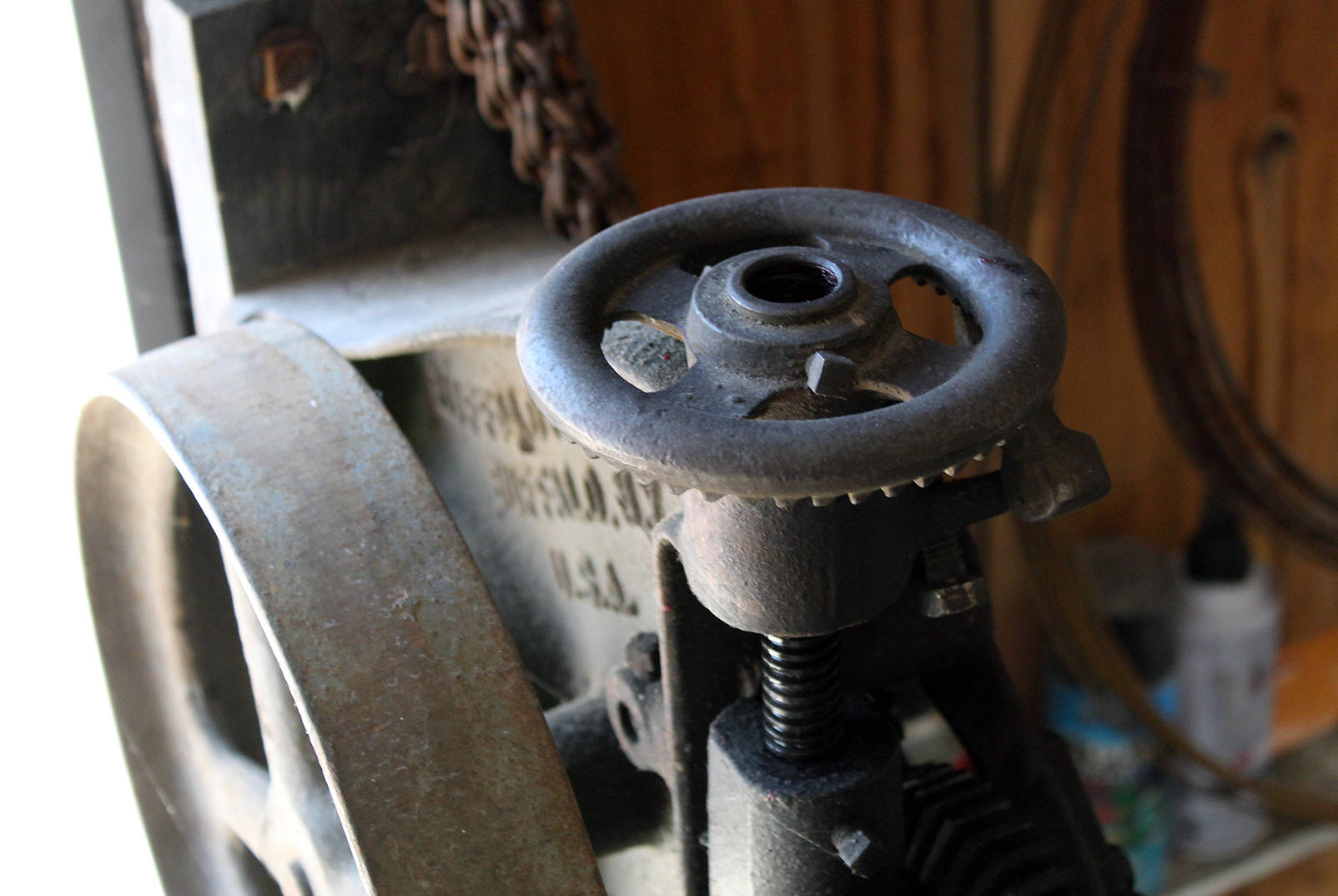
 Raising
and lowering the drill. Rotating the feed wheel (and feed nut) causes the feed
screw to move up or down, thus lifting or lowering the drill as desired by the
mechanic. The feed wheel usually had a small wooden handle mounted on top for
convenience of turning the feed wheel (see photos at right). The wooden handle on
the feed wheel was mounted on a small bolt, thus mechanics should be careful to
avoid applying too much force to the wooden handle while turning the feed wheel by
hand. The feed screw and feed wheel threads should be kept clean and oiled to
allow easy operation of these parts. The wooden handles are often missing or
broken or damaged on these drills. The wooden handle and bolt are very easily made
and replaced. If the owner wants only to bring the drill back into 100%
serviceability and is not concerned with authenticity or restoration, this author
recommends making a replacement wooden handle by modifying a small chain saw file
handle to fit. If it is necessary to make a new wooden feed wheel handle, it is
important to keep the overall length of the handle very short to avoid applying
excessive leverage that might bend the bolt that the handle is mounted on. If
using a file handle to replace the original handle, it will be necessary to trim
the length of the handle so that it is not excessively long.
Raising
and lowering the drill. Rotating the feed wheel (and feed nut) causes the feed
screw to move up or down, thus lifting or lowering the drill as desired by the
mechanic. The feed wheel usually had a small wooden handle mounted on top for
convenience of turning the feed wheel (see photos at right). The wooden handle on
the feed wheel was mounted on a small bolt, thus mechanics should be careful to
avoid applying too much force to the wooden handle while turning the feed wheel by
hand. The feed screw and feed wheel threads should be kept clean and oiled to
allow easy operation of these parts. The wooden handles are often missing or
broken or damaged on these drills. The wooden handle and bolt are very easily made
and replaced. If the owner wants only to bring the drill back into 100%
serviceability and is not concerned with authenticity or restoration, this author
recommends making a replacement wooden handle by modifying a small chain saw file
handle to fit. If it is necessary to make a new wooden feed wheel handle, it is
important to keep the overall length of the handle very short to avoid applying
excessive leverage that might bend the bolt that the handle is mounted on. If
using a file handle to replace the original handle, it will be necessary to trim
the length of the handle so that it is not excessively long.

 Self-feed
operation. Self-feed means that the drill will automatically lower the bit
into the work as the mechanic cranks the drill. Late model post drills almost
always have a self feeding mechanism built into the drill. The self feed
mechanism is necessary because both of the mechanics hands are busy holding the
work and turning the drill crank. An automatic third hand was needed. The
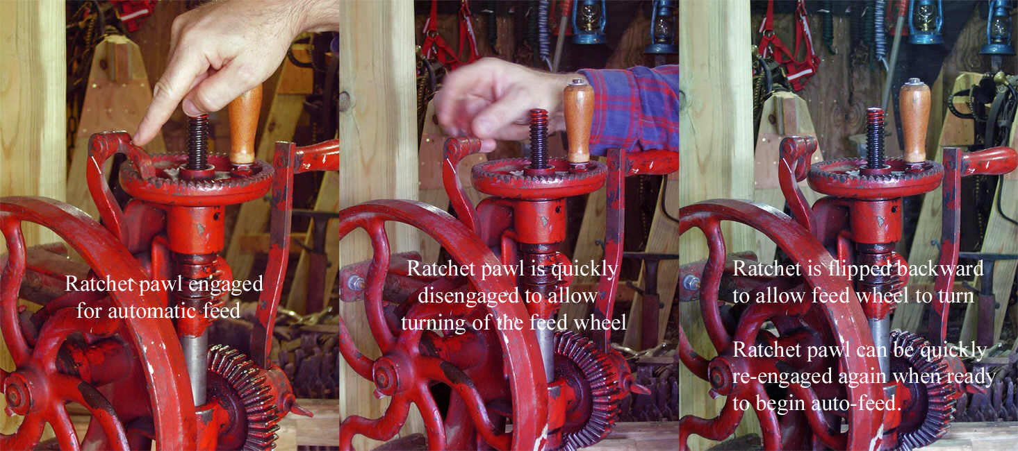
self-feed is engaged by flipping the feed dog (at top of the feed arm) onto the
ratchet teeth at top of the feed wheel. With the feed dog engaged, the self-feed
will automatically lower the spindle and drill bit into the work as the drill is
turning. To raise the spindle, the feed dog is flipped backward off the ratchet
teeth of the feed wheel, and the feed wheel is turned in reverse direction thus
lifting the drill out of the work.
Self-feed
operation. Self-feed means that the drill will automatically lower the bit
into the work as the mechanic cranks the drill. Late model post drills almost
always have a self feeding mechanism built into the drill. The self feed
mechanism is necessary because both of the mechanics hands are busy holding the
work and turning the drill crank. An automatic third hand was needed. The
self-feed is engaged by flipping the feed dog (at top of the feed arm) onto the
ratchet teeth at top of the feed wheel. With the feed dog engaged, the self-feed
will automatically lower the spindle and drill bit into the work as the drill is
turning. To raise the spindle, the feed dog is flipped backward off the ratchet
teeth of the feed wheel, and the feed wheel is turned in reverse direction thus
lifting the drill out of the work.
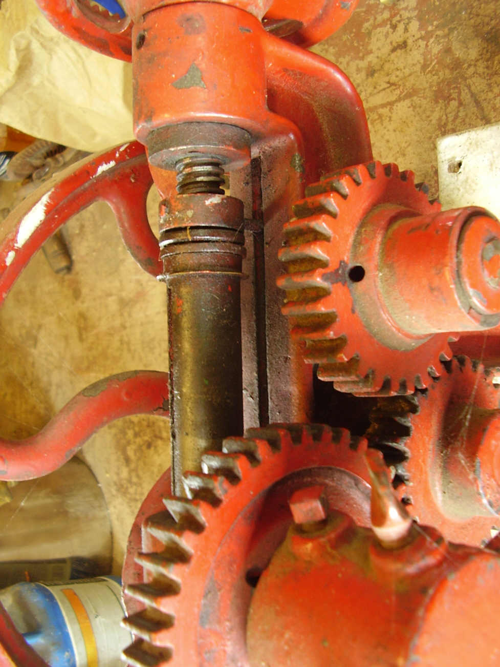
Feed screw. A feed screw connects to the top of the drill spindle through a ball bearing. The ball bearings provide a low friction joint between the feed screw and the drill spindle. The feed screw is threaded through the feed nut inside the upper end of the drill frame. The feed wheel (at top of the drill) is fastened to the upper end of the feed nut with a set screw. The bearing race is fastened to the lower end of the feed screw with a long pin or rivet. The long end of the pin extends through the back of the bearing race and engages in the vertical slot that is machined into the drill frame, thus allowing free vertical travel of the feed screw while at the same time, preventing the feed screw from rotating.
 Feed
arm. The feed arm is bolted loosely to the side of the drill frame. The bolt
is located approximately in the middle of the feed arm, the bolt acting as a pivot
that allows the feed arm to teeter or walk back and forth. A dog (pawl) is riveted
loosely to the top of the feed arm. The dog can be flipped "on" or "off" of the
feed wheel - engaging or disengaging the self feed mechanism as desired by the user. When
the self-feed dog is engaged on the feed wheel, the dog catches against the
ratchet teeth and causes the feed wheel to turn in the down-feed direction. While
traveling the opposite direction, the dog floats over the tops of the ratchet
teeth. Most small post drills had only very limited adjustment of the self-feed
speed - allowing the feed dog to advance the feed wheel by either one or two teeth
at a time.
Feed
arm. The feed arm is bolted loosely to the side of the drill frame. The bolt
is located approximately in the middle of the feed arm, the bolt acting as a pivot
that allows the feed arm to teeter or walk back and forth. A dog (pawl) is riveted
loosely to the top of the feed arm. The dog can be flipped "on" or "off" of the
feed wheel - engaging or disengaging the self feed mechanism as desired by the user. When
the self-feed dog is engaged on the feed wheel, the dog catches against the
ratchet teeth and causes the feed wheel to turn in the down-feed direction. While
traveling the opposite direction, the dog floats over the tops of the ratchet
teeth. Most small post drills had only very limited adjustment of the self-feed
speed - allowing the feed dog to advance the feed wheel by either one or two teeth
at a time.
Lower end of the feed arm rides on the surface of an eccentric wheel. The eccentric wheel is located on hub of either the flywheel or the drive gear, depending on the manufacturer or model of drill. The eccentric wheel provides the necessary motion that causes the feed arm to walk back and forth. The feed arm is held against the eccentric wheel by either spring pressure or gravity.
The feed arm on the red drill shown here has a hooked or bent shape so that the weight of the lower half of the arm holds it against the eccentric wheel on the flywheel hub by force of gravity. In addition, a small adjustable weight is fastened to the lower end of the feed arm to provide limited adjustment of the self-feed, and to provide more weight to hold the feed arm against the eccentric wheel.
 Extra
features found on larger post drills. Quick change gears for multiple drilling
speeds. Greater range of self-feed speeds. Fixed and free pulleys for use with
line shafts. Quick return gears built into the self-feed mechanism for changing
direction of self-feed so that the drill will return itself to the raised position
quickly. Combination of lever feed and self-feed with the option to disconnect the
self-feed - thus allowing the user to quickly lift and lower the drill using the
feed lever. To see a high quality heavy duty post drill with lots of features
(currently waiting for restoration), go here:
Canedy-Otto New No. 16 Drill.
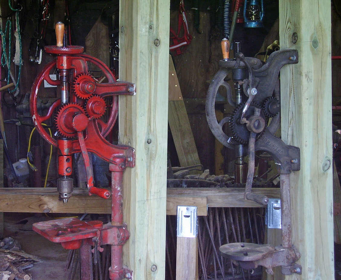
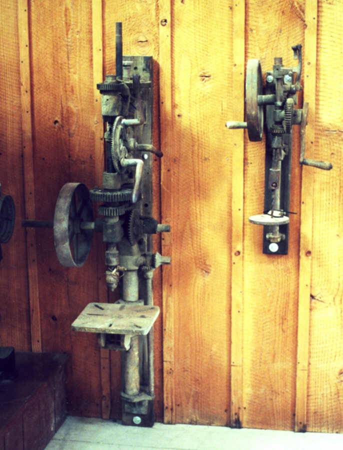
Other features included removable drilling tables that allow a special rack to be
used for drilling tires, and jack shafts to allow changing drilling speeds when
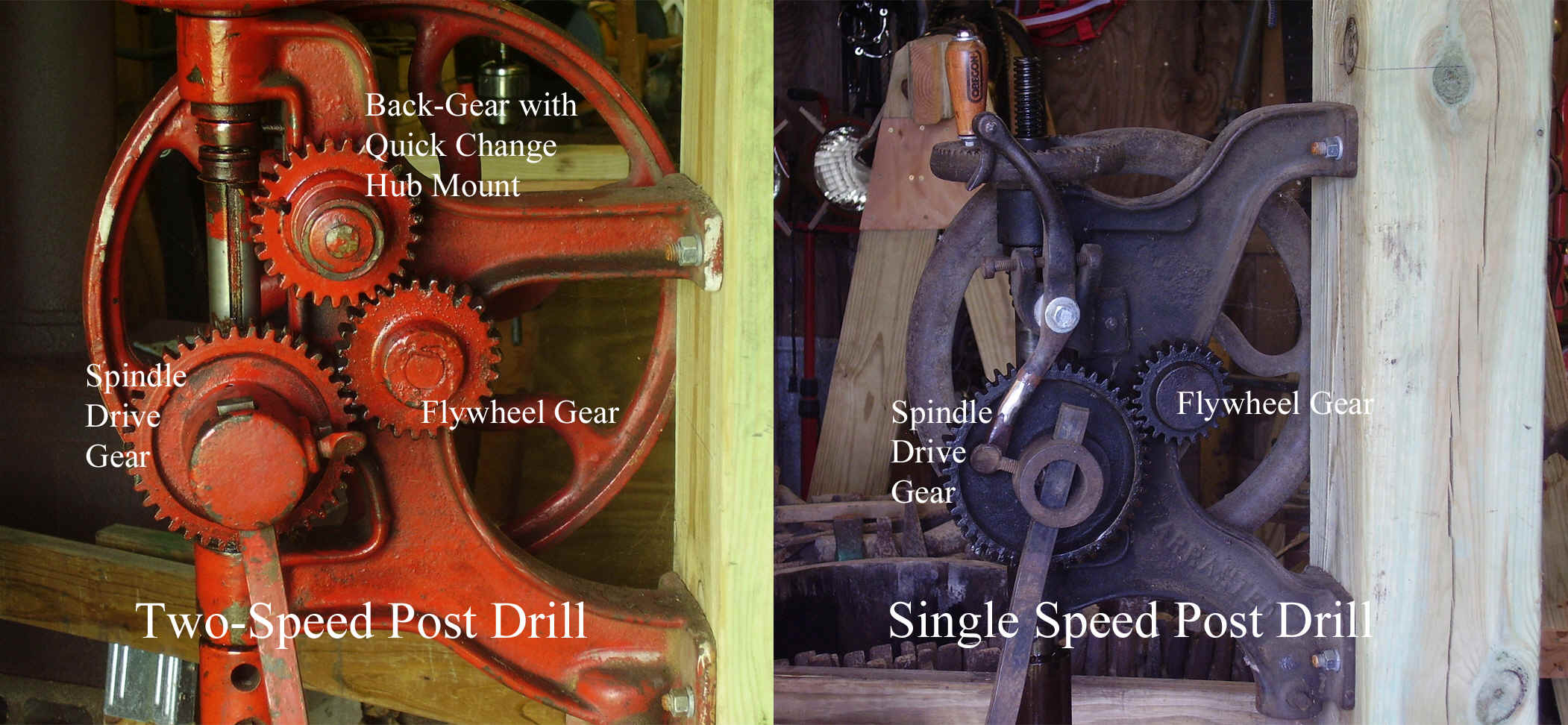
lineshaft power is in use. The two drills seen in the photo at right, belong to
the author. The red drill on the left side of the photo is the two-speed red
drill featured at the top of this page. The black drill is a typical single
speed drill that is most commonly found at flea markets. Take a close look at
these two drills side by side. A third gear can be seen on the red drill. This
third gear is a 'back' gear that allows a second slower speed that allows for
increased torque in heavy drilling while drilling larger holes. Extra gears and
removable crank hubs indicate that the drill has multiple speeds.
Extra
features found on larger post drills. Quick change gears for multiple drilling
speeds. Greater range of self-feed speeds. Fixed and free pulleys for use with
line shafts. Quick return gears built into the self-feed mechanism for changing
direction of self-feed so that the drill will return itself to the raised position
quickly. Combination of lever feed and self-feed with the option to disconnect the
self-feed - thus allowing the user to quickly lift and lower the drill using the
feed lever. To see a high quality heavy duty post drill with lots of features
(currently waiting for restoration), go here:
Canedy-Otto New No. 16 Drill.
Other features included removable drilling tables that allow a special rack to be
used for drilling tires, and jack shafts to allow changing drilling speeds when
lineshaft power is in use. The two drills seen in the photo at right, belong to
the author. The red drill on the left side of the photo is the two-speed red
drill featured at the top of this page. The black drill is a typical single
speed drill that is most commonly found at flea markets. Take a close look at
these two drills side by side. A third gear can be seen on the red drill. This
third gear is a 'back' gear that allows a second slower speed that allows for
increased torque in heavy drilling while drilling larger holes. Extra gears and
removable crank hubs indicate that the drill has multiple speeds.


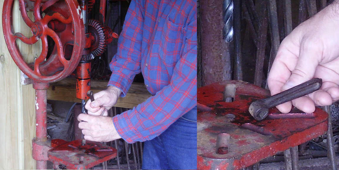
 Two-speed
quick change gears. On post drills that are so equipped, speed changes often
could be effected with; the flip of a lever, unpinning of a spring-loaded pin, or
removing the crank lever and re-installing the crank on another gear. At
right are photos of the author making a speed change to the drill by removing
and re-installing the crank handle on a 'back' gear. In the first photo (near
right) the crank handle and hub are mounted on the large drill spindle drive gear.
This is the most used drive speed for smaller holes. The photo shows a close
comparison of a two-speed drill with back gear, and a single speed drill. The next
photo (middle right) is a composite showing the steps in changing speeds on this
drill. The final photo (far right) shows the crank handle and hub mounted on the
back gear - and the drill is ready for drilling larger holes.
Two-speed
quick change gears. On post drills that are so equipped, speed changes often
could be effected with; the flip of a lever, unpinning of a spring-loaded pin, or
removing the crank lever and re-installing the crank on another gear. At
right are photos of the author making a speed change to the drill by removing
and re-installing the crank handle on a 'back' gear. In the first photo (near
right) the crank handle and hub are mounted on the large drill spindle drive gear.
This is the most used drive speed for smaller holes. The photo shows a close
comparison of a two-speed drill with back gear, and a single speed drill. The next
photo (middle right) is a composite showing the steps in changing speeds on this
drill. The final photo (far right) shows the crank handle and hub mounted on the
back gear - and the drill is ready for drilling larger holes.
Mounting/installing a post drill. This is the most important aspect of setting up and working with post drills - mounting/installing the drill at the most effective and convenient working height. It is best to mount the post drill to a post. Mounting the post drill to a wall presents problems including being an inconvenient location for working, and preventing operation by hand because the hand crank runs too close to the wall and causes injury to the mechanic's hand. The ideal location for a post drill is to mount it to a post or column near the middle (or middle side) of the workshop.
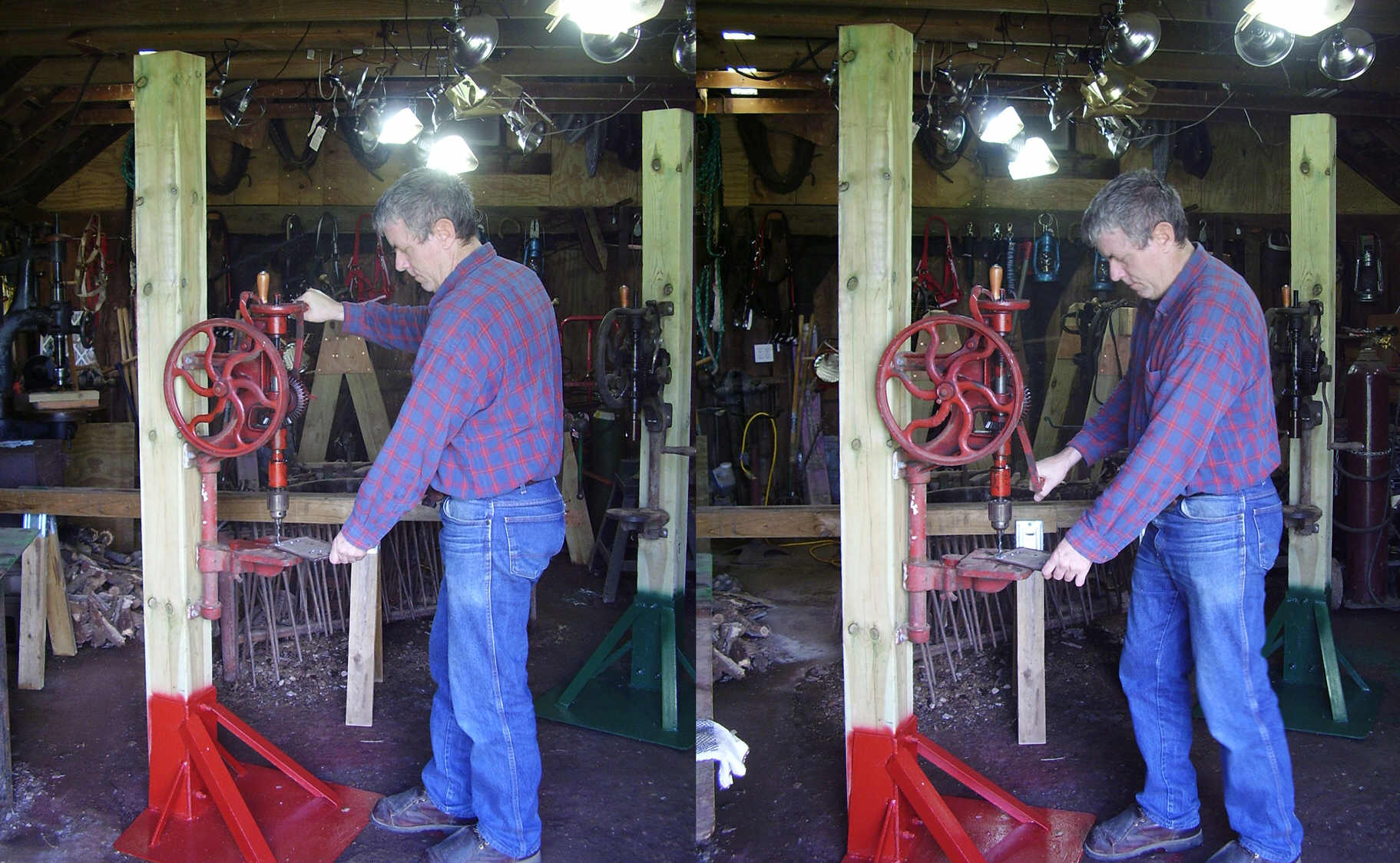
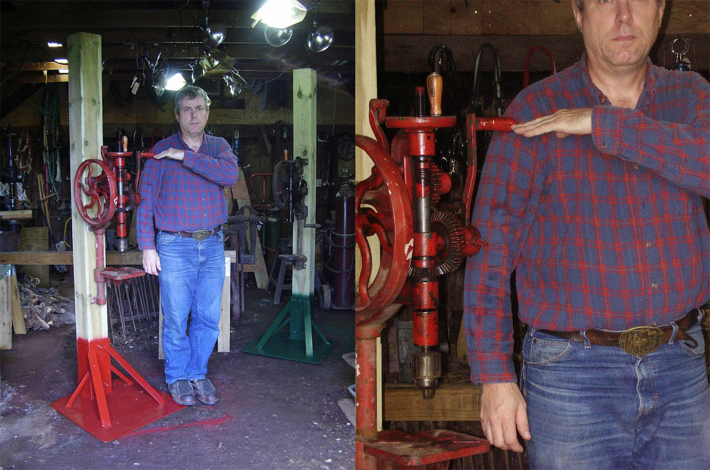 Ideal
mounting height or working height for post drills. The photos (at right) show
a post drill mounted at the easiest and most effective working height. A hand operated post drill requires a
great amount of repetitive and forceful motion to turn the drill in the work. This
force is continuous as long as the drill bit is cutting. This means that the
mechanic must exert force to turn the crank handle throughout every angle of the
handle rotation. While operating the post drill, there are only two comfortable
motions for exerting force - pushing horizontally, and pulling upwards at a 45
degree angle. It is not comfortable to lift with the arm extended, nor is it
comfortable to push downward or upward above the level of the mechanic's
shoulder. Correct drill mounting height takes these physical limitations into
consideration. When planning installation height of a post drill, measure to the
center of the mechanic's shoulder joint to obtain the proper height of the crank
handle, at its highest point of rotation.
Ideal
mounting height or working height for post drills. The photos (at right) show
a post drill mounted at the easiest and most effective working height. A hand operated post drill requires a
great amount of repetitive and forceful motion to turn the drill in the work. This
force is continuous as long as the drill bit is cutting. This means that the
mechanic must exert force to turn the crank handle throughout every angle of the
handle rotation. While operating the post drill, there are only two comfortable
motions for exerting force - pushing horizontally, and pulling upwards at a 45
degree angle. It is not comfortable to lift with the arm extended, nor is it
comfortable to push downward or upward above the level of the mechanic's
shoulder. Correct drill mounting height takes these physical limitations into
consideration. When planning installation height of a post drill, measure to the
center of the mechanic's shoulder joint to obtain the proper height of the crank
handle, at its highest point of rotation.
Measuring for best drill height. With the crank handle installed in the drill at its longest length, rotate the crank handle until it points straight up. Hold the drill in position against the post where it will be mounted, and raise/lower the drill until the crank handle is level with the center of the mechanic's shoulder. Mark positions of the drill mounting holes on the post. Now drill the post and install the drill. The most ideal working positions of the post drill can be seen in the photos at right.
Why did old advertisements and catalogs depict their post drills mounted at eye level (too high)? Many old tool catalogs (including my 1909 Champion Blower & Forge Co. Catalog) have drawings that depict their post drills mounted at, or above eye level. The reason for this is actually quite simple, and it has nothing to do with how these drills were intended to be used. A raised viewing angle perspective creates an impressive/superior viewing aspect which causes the viewer to look up to the item being advertised. Like a great statue of a local hero on horseback � placed on a raised platform high above the public viewing area � it garners respect for the object being viewed. This same effect is used in advertising to cause the intended viewers to look up to the product being advertised � even if only printed in a catalog or newspaper. Most people today mistakenly believe that this is the actual height at which their own drills must somehow be mounted. It doesn�t take a rocket scientist to soon discover that mounting a hand-operated drill so high above the floor actually makes the drill very difficult to use. In reality, a hand-operated post drill is better installed/mounted at a lower height that offers the mechanic more convenient and comfortable access. The tallest height that is comfortable for a man to work with his hands, is no higher than shoulder level. Therefore a post drill should be mounted at a much lower height than suggested by the drawings or engravings of post drills found in old advertisements or catalogs.
Many post drills have spent literally
years sitting around in a pile of junk, collecting dirt and dust. Grease and oil
having long since dried up and hardened, after sitting for so long unused. Dried
grease and oil and dirt will make the post drill very difficult to operate. The
bearings and journals and gears must be thoroughly cleaned and lubricated to bring
the drill back into service. WD-40 or kerosene or other solvents may be used to
soften and dissolve dried grease and oil. Oil holes should be cleaned out
thoroughly to allow oil to be added to bearings and other moving parts. All
bearings and moving parts should be oiled before turning or operating any moving
parts of the drill - even before cleaning is complete. No parts should be forced
to turn unless lubricated first. Some parts might not be accessible due
to being permanently riveted together. The best way to clean permanently joined
parts is to flood the oil holes with oil and thus encouraging the oil to
dissolve
 and wash away dried deposits. This is especially true of the bearing
journals for the flywheel shaft and crank handle drive gears. Gear teeth must be
thoroughly cleaned of all deposits of dried grease and oil and dirt - no matter
how small these deposits might appear to be - because even the smallest deposits
of dried grease and oil will make the drill difficult to turn. After thoroughly
cleaning all moving parts, the drill should be well oiled with good quality oil.
and wash away dried deposits. This is especially true of the bearing
journals for the flywheel shaft and crank handle drive gears. Gear teeth must be
thoroughly cleaned of all deposits of dried grease and oil and dirt - no matter
how small these deposits might appear to be - because even the smallest deposits
of dried grease and oil will make the drill difficult to turn. After thoroughly
cleaning all moving parts, the drill should be well oiled with good quality oil.
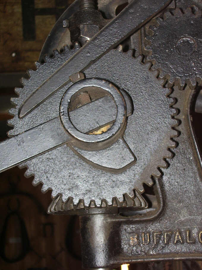
What a difference cleaning and oiling makes. At right is a photo of the gears on the author's Champion Blower & Forge Company Number 98 drill. Look closely at the tiny deposits of dried grease and oil that have formed inside the gear teeth. These deposits made it very difficult for the author to turn the crank handle to operate this drill by hand. After cleaning and oiling, this drill turned so easily that it is now normal to be able to start the drill turning, let go of the crank, and the drill continues to turn on its own for several seconds. The hand cranked drill requires a large amount of effort just to drill each hole. Any friction due to dirty bearings or gears will make large drilling tasks almost unbearable. A well maintained post drill will continue turning for several seconds after letting go of the crank handle, and will make the task of drilling much easier.

 Where to buy a post drill. Post drills can be found at draft horse
auctions, steam power and antique engine shows and related flea markets and swap
meets, and at some farm auctions and estate auctions where the owner used older
tools.
Where to buy a post drill. Post drills can be found at draft horse
auctions, steam power and antique engine shows and related flea markets and swap
meets, and at some farm auctions and estate auctions where the owner used older
tools.
What to look for - what to avoid. Look for drills that are complete - all parts present and in good working condition. Beware! Many of these old drills have been damaged and dismembered by recent owners and some drills might be in crippled or unserviceable condition. Parts might be worn out or missing entirely. Look for bearing journals (any joint that a moving part passes through) that are not worn out or loose. Replacing worn out bearing babbitt is a job for experts only. Look for gear teeth that are NOT worn out, badly pitted, or broken. Operate the drill and to determine condition of parts - look for smooth movement of parts. Avoid any drill if movement feels like parts are grinding or rough. Set screw threads in the drill chuck should be in good condition - NOT stuck or stripped or loose.
DON'T BUY a drill if any of the following conditions are present: feed wheel missing or broken, feed arm missing or broken, drill spindle bent or missing or broken, flywheel missing or broken, lower frame or table missing or broken, gears missing or broken or teeth broken or excessively corroded or pitted, broken or worn out bearing connection between feed screw and spindle or bearing balls missing at this joint, or any other parts missing or broken. Repairing these old drills is a job for expert machinists and mechanics - NOT beginners! If a person must ask, they are not experts.
Additional resources to learn about chucks, arbors, and tooling for drills. See the author's description of taper shank tooling here: Morse Taper . The Jacobs Chuck Company website offers the manufacturers recommended procedures for removing and installing chucks and arbors. The author's Jacobs Chuck page shows a Jacobs chuck disassembled, reassembled, and installation of taper shank arbors.
ATTENTION! - Hobbyists: get help! It is not possible to teach you over the internet. Find a local machinery supplier that can assess your tool requirements for you. Beginners must learn to distinguish between the different sizes of shank ends and arbor ends. The shank is the part that is inserted into the socket of a drill press spindle or in the bit end of a drill chuck. The arbor end is the short tapered or threaded end that fits into the mounting hole of the drill chuck. Learn to use rules, tape measures, and calipers, or find someone to measure your tools and machines for you.
There is very little documentation on these old drills. The information that appears on this webpage is mostly from my own observation. What you see here is everything I have. With exception of a couple of antique catalogues and old magazines, there is no other information available. The purpose of this page is to introduce the new user to these old drills. Setting up and using a post drill requires common sense. In the bygone era when these tools were made, people were much more intelligent then they are today. They understood how to set up and use the tools that they made or bought. They didn't need a 27 page booklet explaining to them for example, how to use a hammer or a wrench. If the modern buyer can't figure out on their own how to use these drills, then they have no business getting one. Tools are useless and dangerous in the hands of a dummy who lacks common sense. There are no instructions for these old tools. When you buy an antique, you are on your own as far as learning how to take care of it and using it. If you need more information on your drill, you are out of luck as it most likely doesn't exist.
Drills shown on this page:
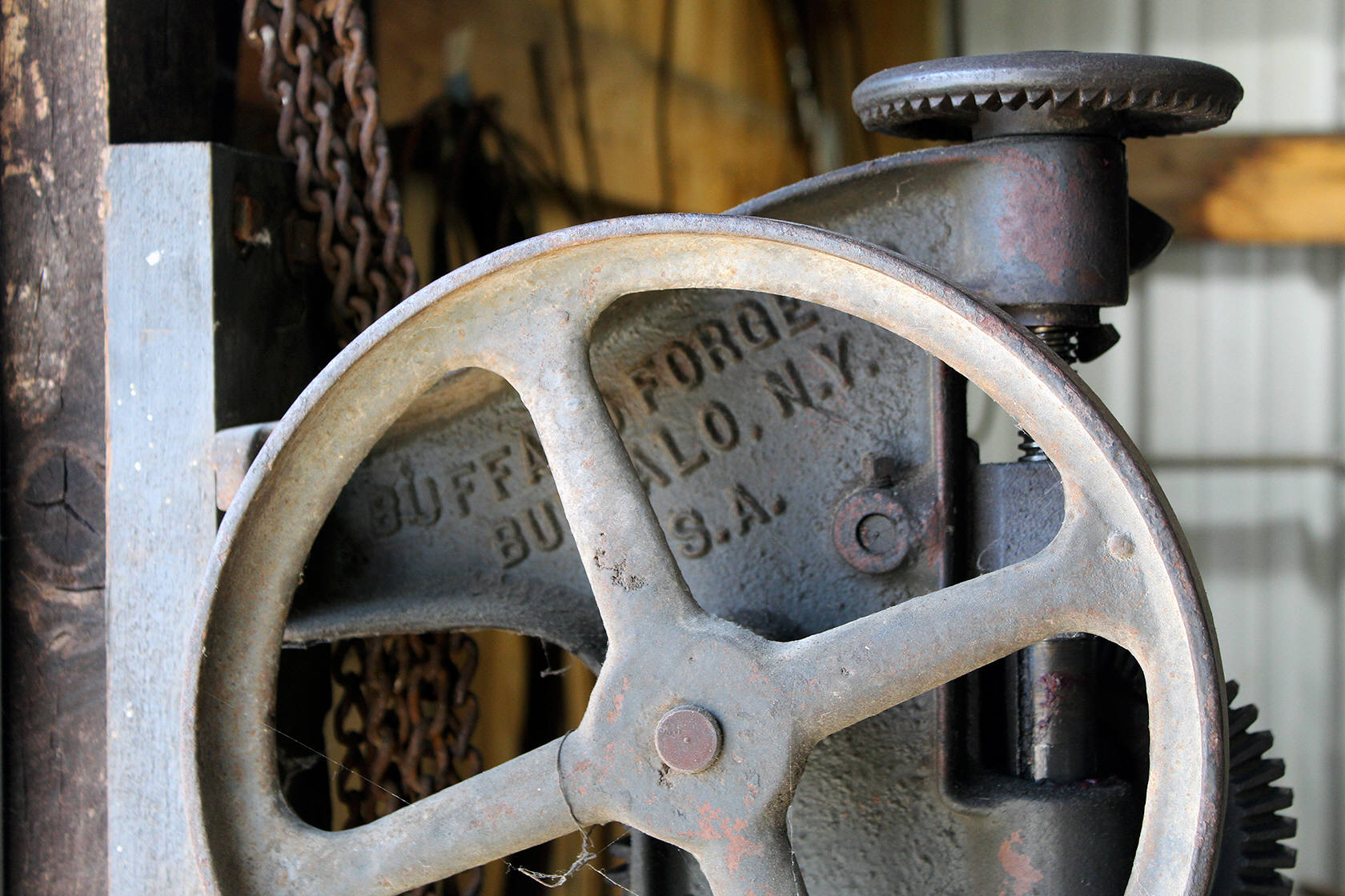
Buffalo Forge No. 61
Buffalo Forge No. 616 NEW on October 8, 2021
Canedy-Otto No. 18
Canedy-Otto No. 19
Champion Blower & Forge No. 7 NEW on October14, 2021
Champion Blower & Forge No. 98
Champion Blower & Forge No. 200
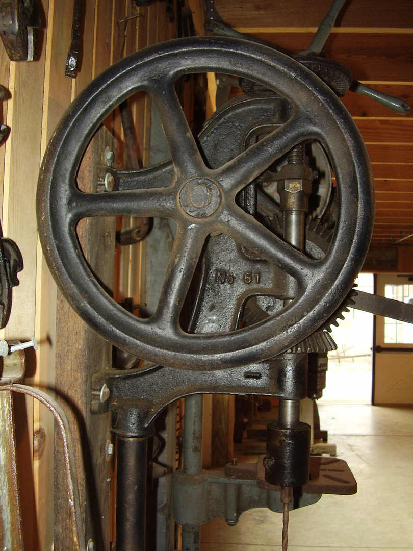
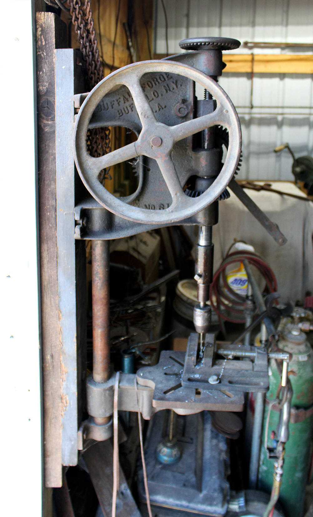
 Buffalo
Forge Number 61 Post Drill. The Number 61 is a small inexpensive
light-duty post drill that was made for small home workshops and small farm shops.
The drill chuck was a simple screw chuck with a 1/2-inch socket for use with
straight shank drill bits. The chuck featured a recessed pocket for the set screw
so that the set screw would not protrude outward and thus present a safety hazard
to the mechanic while operating the drill. This was a safety feature provided by
the better quality drills. The Number 61 was an inexpensive drill with very simple
features including; small brass feed wheel knob, single-speed, a short crank
handle, and a simple cam and lever auto-feed mechanism. The Buffalo Forge Number
61 post drill is a 12-inch drill press - that is, the Number 61 will drill to the
center of a 12-inch circle. The Number 61 has an up and down run of approximately
3 inches.
Buffalo
Forge Number 61 Post Drill. The Number 61 is a small inexpensive
light-duty post drill that was made for small home workshops and small farm shops.
The drill chuck was a simple screw chuck with a 1/2-inch socket for use with
straight shank drill bits. The chuck featured a recessed pocket for the set screw
so that the set screw would not protrude outward and thus present a safety hazard
to the mechanic while operating the drill. This was a safety feature provided by
the better quality drills. The Number 61 was an inexpensive drill with very simple
features including; small brass feed wheel knob, single-speed, a short crank
handle, and a simple cam and lever auto-feed mechanism. The Buffalo Forge Number
61 post drill is a 12-inch drill press - that is, the Number 61 will drill to the
center of a 12-inch circle. The Number 61 has an up and down run of approximately
3 inches.
Feed wheel knob made of brass. The feed wheel handle knob is made of brass and threaded into the feed ratchet wheel. The knob is small and attractive in appearance, but it does not rotate and thus it could be uncomfortable and difficult to use for multiple drilling tasks.
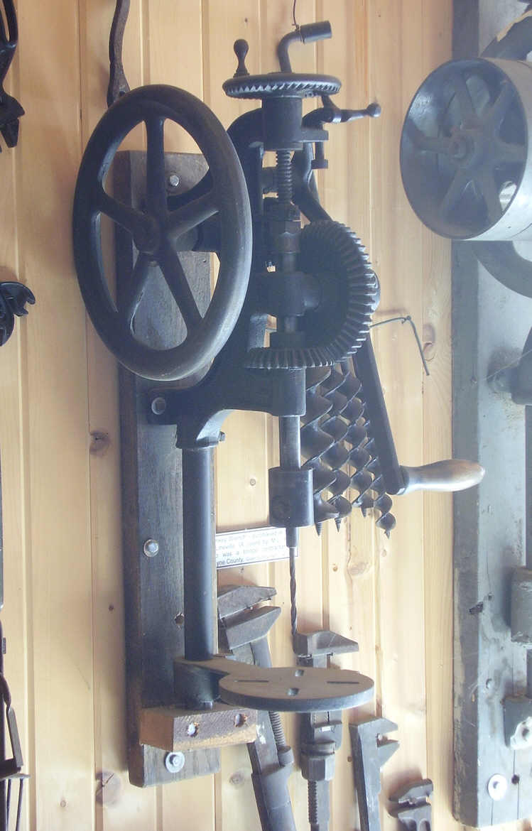
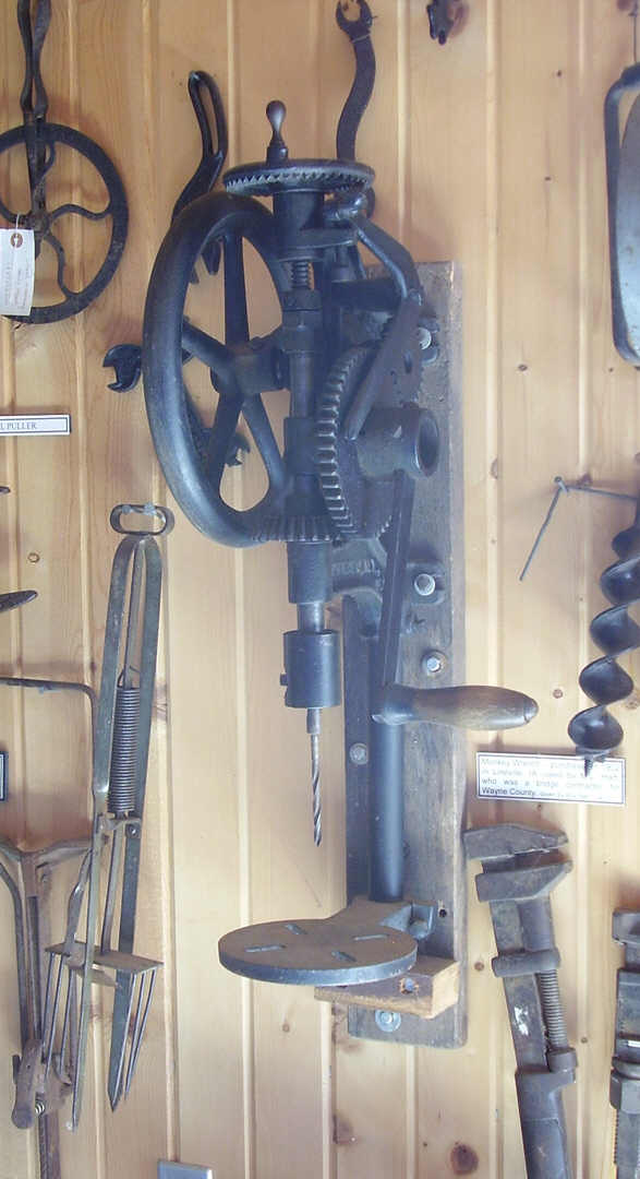
Drill mounting. This drill was photographed in a museum where, it was mounted on a 2" x 5" plank, and the plank mounted on the wall. The plank is too thin for effective use of the drill because it places the drill too close to the wall and causes the flywheel to rub against the wall. The close placement also causes the mechanics hand to strike the wall while turning the hand crank. It would be best to mount this drill on a 6" x 6" post or column. If necessary to mount the drill on the wall, it would be better to double the thickness of the plank to 3-1/2" to 4" thick, thus allowing the flywheel to turn freely and to allow more space to allow the crank handle to be used without coming in contact with the wall.


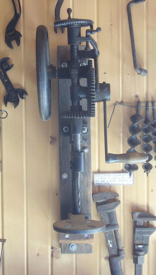
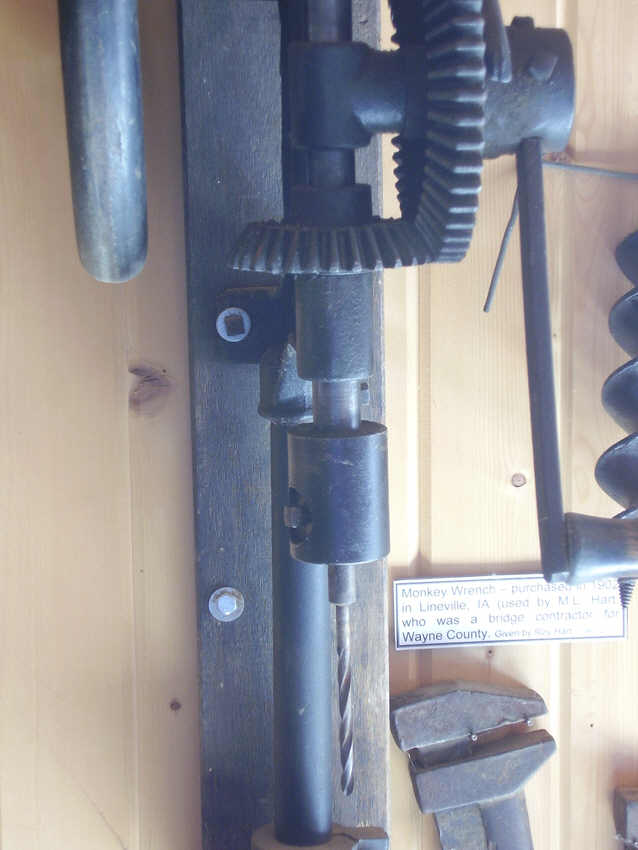
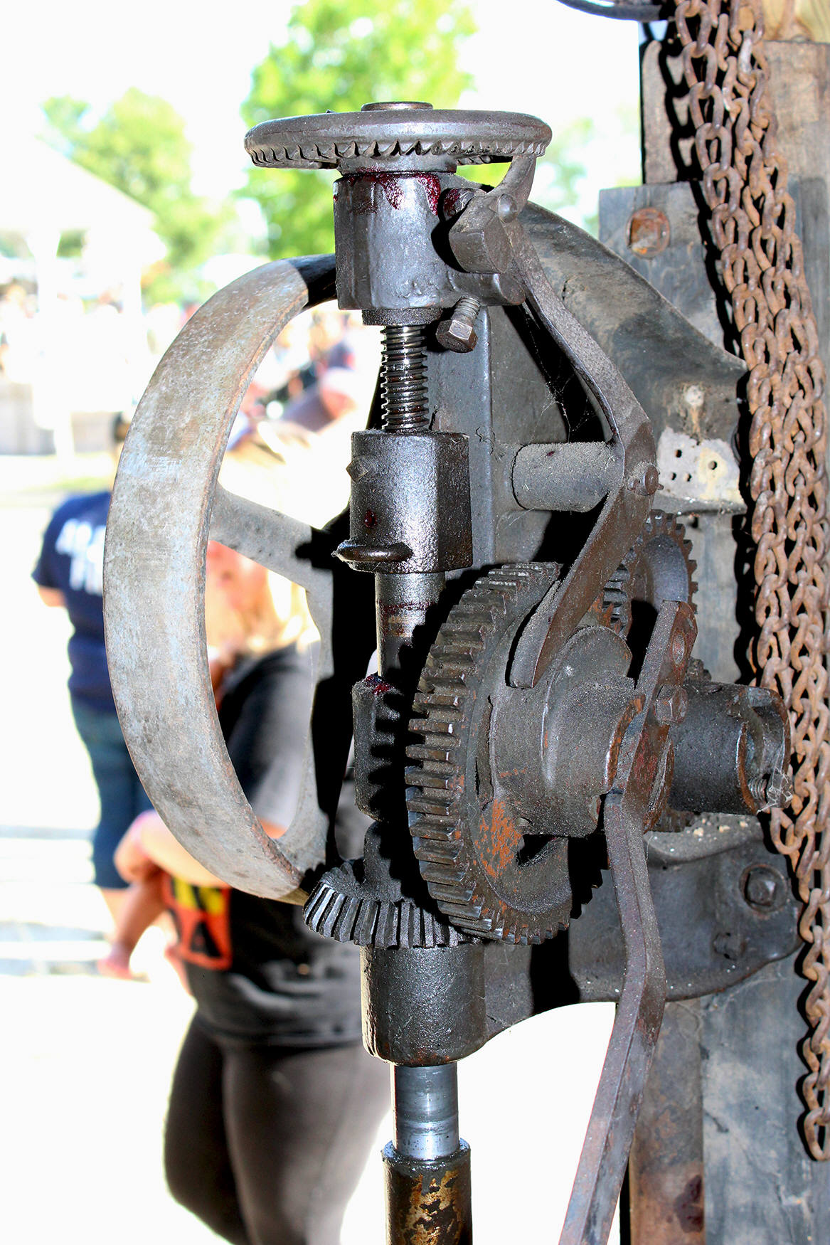
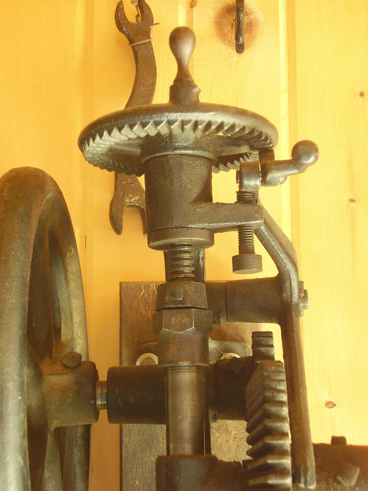 Ratcheting
auto-feed mechanism. The thumbnail photos (at right) show the racheting
auto-feed mechanism. The ratchet teeth of the feed wheel are faced downward on
this drill. The cam is a simple eccentric lobe that has been cast and machined on
the side of the spindle drive gear. The rocker arm operates by gravity - the heavy
end riding against the eccentric cam lobe. The ratchet dog riveted to the upper
end of the rocker arm is also gravity operated. A little ball on the end of the
ratchet dog pulls down on the rachet dog, thus lifting the pointed end of the
ratchet dog up into the ratchet teeth cut in the bottom of the feed wheel. The
movement of the rocker arm can be adjusted to limit the amount of movement or
distance that the drill spindle feeds into the work with each rotation of the
drill. In the two photos (near right) a small ear is molded onto the upper frame
of the drill, under the ratcheting feed wheel. This little frame extension fits
underneath the upper end of the rocker arm - directly under the ratchet dog and
feed wheel. A small thumbscrew is threaded into the frame extension. The
thumbscrew presses against the bottom surface of the upper end of the rocker arm.
By threading the thumbscrew in or out, the movement of the rocker arm can be
increased or decreased as desired, to adjust the number of teeth that the ratchet
dog will move the feed wheel with each rotation of the drill crank handle.
Movement of the feed wheel can be adjusted to move 1-3 teeth with each revolution
of the drill crank handle. The crank handle adjustment screw is also clearly
visible in the close-up photo (at far right). Loosening the set screw near the
center of the gear allows the handle to be removed or adjusted in length.
Ratcheting
auto-feed mechanism. The thumbnail photos (at right) show the racheting
auto-feed mechanism. The ratchet teeth of the feed wheel are faced downward on
this drill. The cam is a simple eccentric lobe that has been cast and machined on
the side of the spindle drive gear. The rocker arm operates by gravity - the heavy
end riding against the eccentric cam lobe. The ratchet dog riveted to the upper
end of the rocker arm is also gravity operated. A little ball on the end of the
ratchet dog pulls down on the rachet dog, thus lifting the pointed end of the
ratchet dog up into the ratchet teeth cut in the bottom of the feed wheel. The
movement of the rocker arm can be adjusted to limit the amount of movement or
distance that the drill spindle feeds into the work with each rotation of the
drill. In the two photos (near right) a small ear is molded onto the upper frame
of the drill, under the ratcheting feed wheel. This little frame extension fits
underneath the upper end of the rocker arm - directly under the ratchet dog and
feed wheel. A small thumbscrew is threaded into the frame extension. The
thumbscrew presses against the bottom surface of the upper end of the rocker arm.
By threading the thumbscrew in or out, the movement of the rocker arm can be
increased or decreased as desired, to adjust the number of teeth that the ratchet
dog will move the feed wheel with each rotation of the drill crank handle.
Movement of the feed wheel can be adjusted to move 1-3 teeth with each revolution
of the drill crank handle. The crank handle adjustment screw is also clearly
visible in the close-up photo (at far right). Loosening the set screw near the
center of the gear allows the handle to be removed or adjusted in length.
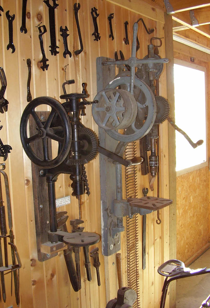
 The
Buffalo Forge Number 61 is a small post drill. Take a look in the photo
(middle right). The number 61 is shown mounted to a wall beside the medium size
Canedy-Otto Number 19 post drill. The Buffalo Forge number 61 was made for small
drilling jobs in the home workshop or small farm shop. Scroll on down near the
bottom of this page for a couple photos of a small farm home workshop - for an
example of the setting where this drill might have been used. Model number of the
drill can be seen in the photo (near right) by looking through the bottom right
spokes of the flywheel.
The
Buffalo Forge Number 61 is a small post drill. Take a look in the photo
(middle right). The number 61 is shown mounted to a wall beside the medium size
Canedy-Otto Number 19 post drill. The Buffalo Forge number 61 was made for small
drilling jobs in the home workshop or small farm shop. Scroll on down near the
bottom of this page for a couple photos of a small farm home workshop - for an
example of the setting where this drill might have been used. Model number of the
drill can be seen in the photo (near right) by looking through the bottom right
spokes of the flywheel.
This drill is in great shape and appears to be almost complete except for the lower pipe frame bracket. The bracket appears to have been replaced or substituted with a wooden block, and this wooden block seems well designed for the purpose. All parts on this drill appear to work properly.
 Where
to see this drill: Prairie Trails Museum of Wayne Country. Highway 2 East,
P.O. Box 104, Corydon, Iowa, USA.
www.prairietrailsmuseum.org Located on highway 2. Look for the red barn with
the steam traction engine in front.
Where
to see this drill: Prairie Trails Museum of Wayne Country. Highway 2 East,
P.O. Box 104, Corydon, Iowa, USA.
www.prairietrailsmuseum.org Located on highway 2. Look for the red barn with
the steam traction engine in front.


 Buffalo
Forge No. 616 Post Drill.
Buffalo
Forge No. 616 Post Drill.
The Buffalo Forge number 616 is a small lower price drill that would have been found in many home garages or small workshops. Like all companies during the previous era, every company had a selection of drills that ranged from high price to low price. Prices were based on size, quality, drilling capacity and number of features. Most small home workshops needed a simple inexpensive drill. The Buffalo Forge Number 616 filled this need for a good quality small inexpensive two-speed drill for the small home or farm workshop.

 This
drill must be mounted to a post NOT a wall!
This is because the crank
handle rotates far enough to the rear that the crank handle and the mechanics
hand would scuff the wall as the handle reaches its most rearward position of
rotational travel. And if the crank handle is installed on the backgear for
higher torque operation while the drill is mounted to a wall, the crank handle
would strike the wall and would be blocked from rotation altogether. This can be
avoided by checking clearance before bolting the post drill permanently in
place. Mount the crank handle to the rear-most gear, (in this case, install the
crank handle on the back gear) then check the full operation of the drill at the
intended mounting location before permanently bolting the post drill in place.
Grab the crank handle and rotate it a full 360 degrees and make sure nothing
interferes with the handle as it rotates completely around in a full circle.
This crank clearance rule is the same for most post drills.
This
drill must be mounted to a post NOT a wall!
This is because the crank
handle rotates far enough to the rear that the crank handle and the mechanics
hand would scuff the wall as the handle reaches its most rearward position of
rotational travel. And if the crank handle is installed on the backgear for
higher torque operation while the drill is mounted to a wall, the crank handle
would strike the wall and would be blocked from rotation altogether. This can be
avoided by checking clearance before bolting the post drill permanently in
place. Mount the crank handle to the rear-most gear, (in this case, install the
crank handle on the back gear) then check the full operation of the drill at the
intended mounting location before permanently bolting the post drill in place.
Grab the crank handle and rotate it a full 360 degrees and make sure nothing
interferes with the handle as it rotates completely around in a full circle.
This crank clearance rule is the same for most post drills.
Alternative mounting method - when the owner wants to install the post drill along a section of wall where there is no post. Construct an artificial post from 6 x 6" lumber, or by bolting together four pieces of 2" x 6" lumber to build up a 6" x 6" post. Bolt the artificial post to the section of wall where it is desired to locate the drill. The post drill is heavy and vibrates during use, so bolt the artificial post to the wall strongly. Then mount the post drill to the artificial post. Bolting a 6" x 6 post to a wall and then mounting the post drill to the artificial post creates the offset necessary to allow the crank handle to rotate freely as though it was installed on a free-standing post.
Two-speeds means that this drill can be quickly and easily configured to operate at high drilling speed low-torque or low speed high-torque. This was accomplished by loosening a mounting bolt and moving the crank handle to either the large front gear or to the smaller back gear. The high or low torque translates to how much leverage the mechanic gains while turning the hand crank. At the low speed high torque configuration, the smaller back gear would operate the drill at a slower speed (lower RPM) and the mechanic would gain more leverage for turning the crank, thus making it easier to force a larger drill bit through the work. For smaller bits this high-torque was not needed, and the drill could be operated with a high speed low-torque configuration to turn the drill at a higher RPM.
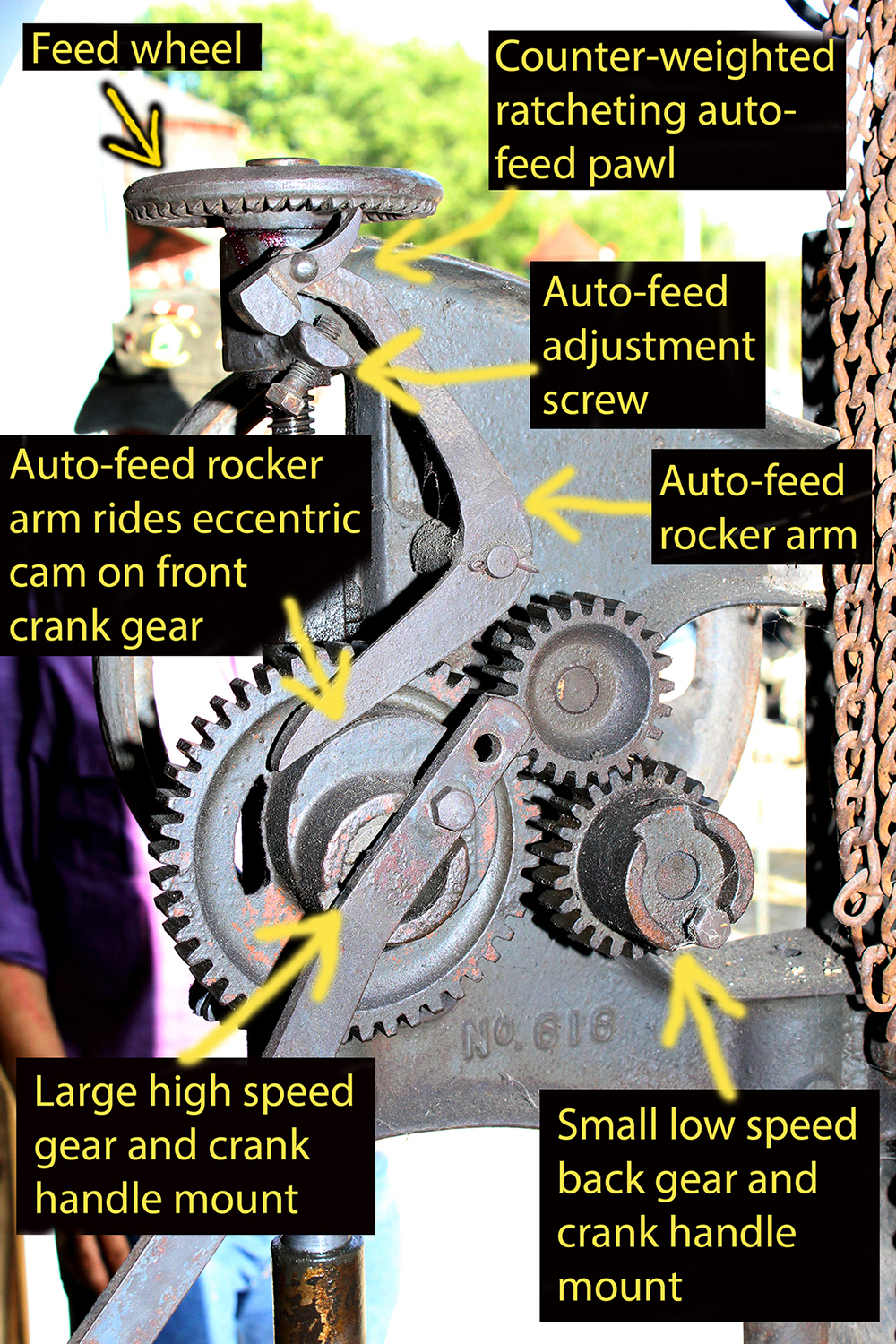
 Auto-feed.
The Buffalo Forge 616 has an auto-feed mechanism to automatically force
the drill bit into the work while the mechanic is cranking the drill. The
auto-feed mechanism has four main components, a rocker arm, eccentric cam,
counter weighted ratchet pawl, and a feed wheel with ratchet teeth that rotates
to raise of lower the drill spindle into the work. The rocker arm simply pivots
in its center on a bolt, the lower end of the rocker arm rides by gravity
against the eccentric cam that is cast into the side of the large high speed
crank gear. The upper end of rocker arm has a counter weighted ratchet pawl that
is held up by gravity against the ratchet teeth in the underside of the feed
wheel. After drilling is complete, the mechanic will need to rotate the feed
wheel by hand to lift the drill bit out of the work. There is no speed handle to
help spin the wheel, so the mechanic must hold the counter-weighted pawl away
from the feed wheel teeth with one hand while rotating the feed wheel with the
other hand.
Auto-feed.
The Buffalo Forge 616 has an auto-feed mechanism to automatically force
the drill bit into the work while the mechanic is cranking the drill. The
auto-feed mechanism has four main components, a rocker arm, eccentric cam,
counter weighted ratchet pawl, and a feed wheel with ratchet teeth that rotates
to raise of lower the drill spindle into the work. The rocker arm simply pivots
in its center on a bolt, the lower end of the rocker arm rides by gravity
against the eccentric cam that is cast into the side of the large high speed
crank gear. The upper end of rocker arm has a counter weighted ratchet pawl that
is held up by gravity against the ratchet teeth in the underside of the feed
wheel. After drilling is complete, the mechanic will need to rotate the feed
wheel by hand to lift the drill bit out of the work. There is no speed handle to
help spin the wheel, so the mechanic must hold the counter-weighted pawl away
from the feed wheel teeth with one hand while rotating the feed wheel with the
other hand.


 The
Buffalo 616 was designed to [not] have a speed handle on the spindle wheel at top of the
drill for quickly raising and lowering the spindle. Another feature that was
omitted to keep price down was the method of retaining the drill bit, the chuck
has a portruding drill bit set screw rather than a more expensive recessed
(counter-sunk) chuck. Despite these omissions, this drill works like any other
small post drill. The photos at right show the top of the spindle wheel - there
is no place to mount a speed handle because the drill was not designed for using
a speed handle. The photos at right also show the portruding drill bit set
screw. The mechanic must take care at all times to keep hands and clothing away
from this set screw while the drill is spinning.
The
Buffalo 616 was designed to [not] have a speed handle on the spindle wheel at top of the
drill for quickly raising and lowering the spindle. Another feature that was
omitted to keep price down was the method of retaining the drill bit, the chuck
has a portruding drill bit set screw rather than a more expensive recessed
(counter-sunk) chuck. Despite these omissions, this drill works like any other
small post drill. The photos at right show the top of the spindle wheel - there
is no place to mount a speed handle because the drill was not designed for using
a speed handle. The photos at right also show the portruding drill bit set
screw. The mechanic must take care at all times to keep hands and clothing away
from this set screw while the drill is spinning.


 The
Buffalo No. 616 shown here belongs to the blacksmith at the Wheelwrights at Old
Threshers MacMillan Park in Mt. Pleasant, Iowa. The model "No. 616" can be seen
in one of the photos at right. The model number is cast into both sides of the
bottom of the drill frame.
The
Buffalo No. 616 shown here belongs to the blacksmith at the Wheelwrights at Old
Threshers MacMillan Park in Mt. Pleasant, Iowa. The model "No. 616" can be seen
in one of the photos at right. The model number is cast into both sides of the
bottom of the drill frame.


 Canedy-Otto
Number 18 Post Drill. The large drill in these photos (photos at
left) is a Canedy-Otto #18. The #18 is a very large post drill that will stand
over 6 feet tall when mounted to a post or wall at a comfortable working height.
The #18 is similar in size and design compared with the author's New #16 shown on
the restoration page att Canedy-Otto
New No. 16 Drill..Both drills still have their original Western Chief Safety
Chucks, and the #18 has an old Jacobs chuck fastened in the Safety Chuck, thus
allowing the drill to accept modern drill bits. The chuck key is tied to the
Jacobs chuck arbor with wire to prevent its loss while the museum prepares to move
this drill to a more permanent display. I could not positively identify the
smaller drill in the photo but I did notice that the smaller drill uses the same
Canedy-Otto Western Chief Safety Chuck as the #18..
Canedy-Otto
Number 18 Post Drill. The large drill in these photos (photos at
left) is a Canedy-Otto #18. The #18 is a very large post drill that will stand
over 6 feet tall when mounted to a post or wall at a comfortable working height.
The #18 is similar in size and design compared with the author's New #16 shown on
the restoration page att Canedy-Otto
New No. 16 Drill..Both drills still have their original Western Chief Safety
Chucks, and the #18 has an old Jacobs chuck fastened in the Safety Chuck, thus
allowing the drill to accept modern drill bits. The chuck key is tied to the
Jacobs chuck arbor with wire to prevent its loss while the museum prepares to move
this drill to a more permanent display. I could not positively identify the
smaller drill in the photo but I did notice that the smaller drill uses the same
Canedy-Otto Western Chief Safety Chuck as the #18..
 The
Canedy-Otto Number 18 weighed approximately 400 pounds. Back gears allow quick
speed changes and multiple drilling spindle speeds. Free and fixed pulleys allowed
the Number 18 to be powered by line shaft in the shop, and a hand crank allowed
the drill to be powered by hand when the line shaft was not running. A feed handle
with three arms allowed the operator to apply feed pressure by hand while the
drill was operating on line shaft power - thus allowing fast operation similar to
the modern motorized drill press.
The
Canedy-Otto Number 18 weighed approximately 400 pounds. Back gears allow quick
speed changes and multiple drilling spindle speeds. Free and fixed pulleys allowed
the Number 18 to be powered by line shaft in the shop, and a hand crank allowed
the drill to be powered by hand when the line shaft was not running. A feed handle
with three arms allowed the operator to apply feed pressure by hand while the
drill was operating on line shaft power - thus allowing fast operation similar to
the modern motorized drill press.
Both drills described here (photos at left) are incomplete - missing parts. The larger #18 is missing the big flywheel that was originally attached to the top of the vertical shaft (at top of the drill). The small drill is missing the feed wheel - the feed wheel would have been located on top of the drill spindle. Compare the the larger drill at left, with the Champion drills in catalog images above. The larger Champion drills have a large horizontal flywheel mounted on top of the drill - this flywheel is missing from the Canedy-Otto drill at left. Also compare the smaller drill at left, with the farmer's workshop drill at right. The horizontal spindle feed wheel and handle are clearly visible on top of the drill in the photo at right. When buying an old drill, it is important to inspect the tool to be sure all parts are present and intact.

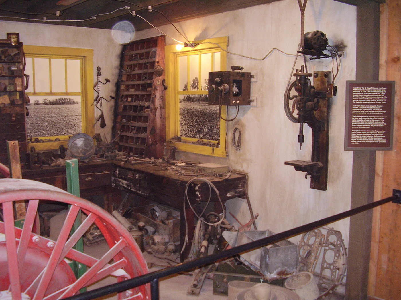
 Farmer's
home workshop. Another small hand cranked drill (photo at right) is found in
the farmer's shop exhibit in Museum A. The thumbnail photos at left show the
entire display as it might have appeared in the farmers barn or work shed. Small
post drills were often purchased by mail order as part of a tool kit along with
some small blacksmithing tools. These are just a small sample of some of the hand
tools that would have been found in a small workshop on a farm around 1900.
There are hand cranked post drills in almost every workshop at Old Threshers.
Before the era of electricity, the hand cranked drill offered the simplest and
easiest way to perform small drilling jobs. Visitors will see these drills in use
throughout the Old Threshers museum displays and living history workshops.
Farmer's
home workshop. Another small hand cranked drill (photo at right) is found in
the farmer's shop exhibit in Museum A. The thumbnail photos at left show the
entire display as it might have appeared in the farmers barn or work shed. Small
post drills were often purchased by mail order as part of a tool kit along with
some small blacksmithing tools. These are just a small sample of some of the hand
tools that would have been found in a small workshop on a farm around 1900.
There are hand cranked post drills in almost every workshop at Old Threshers.
Before the era of electricity, the hand cranked drill offered the simplest and
easiest way to perform small drilling jobs. Visitors will see these drills in use
throughout the Old Threshers museum displays and living history workshops.
Where to see these drills: Old Threshers grounds, Heritage Museum A. The museums are located near center of the park.
 Old Threshers Reunion in Mount Pleasant, Iowa, USA, is a very large
antique steam power and steam tractor show that is held once each year during the
Labor Day holiday weekend. Visitors to Old Threshers' will find a steam tractors,
steam locomotives, agricultural equipment, and steam power industrial machinery in
operation throughout the entire event. Visitors can ride on the restored steam
trains and electric trolleys. Flea markets offer antique and modern tools for
sale. Antique steam, gasoline, and oil engines and tractors are offered for sale
as restoration prospects. To learn more about Old Threshers' Reunion go here:
http://www.oldthreshers.org/
Old Threshers Reunion in Mount Pleasant, Iowa, USA, is a very large
antique steam power and steam tractor show that is held once each year during the
Labor Day holiday weekend. Visitors to Old Threshers' will find a steam tractors,
steam locomotives, agricultural equipment, and steam power industrial machinery in
operation throughout the entire event. Visitors can ride on the restored steam
trains and electric trolleys. Flea markets offer antique and modern tools for
sale. Antique steam, gasoline, and oil engines and tractors are offered for sale
as restoration prospects. To learn more about Old Threshers' Reunion go here:
http://www.oldthreshers.org/
 Canedy-Otto
No. 19 Post Drill. (Photos at left LINK REPAIRED October 7th, 2021) The Canedy-Otto Number 19 is
a medium size post drill that can be powered by lineshaft or by hand cranking.
This is one of Canedy-Otto's professional lineup of drills, and were intended for
professional blacksmiths, mechanic shops, and light manufacturing. These drills
featured a four-handle feed lever for fast raising and lowering of the drill when
lineshaft power was in use. The Number 19 was intended for use with lineshaft
power, but also featured a hand crank for operating the drill when lineshaft power
was stopped. This section has serious flaws and will be re-written. The auto-feed mechanism does not include any means for quickly
raising or lowering the drill spindle - no feed wheel such as one would see
mounted horizontally on top of the red post drill at top of this page. The only
way to lift the drill feed was by engaging the four-handled feed lever and using
this lever to lift the drill out of the work. The Canedy-Otto Number 19 will drill
to the center of a 17-inch circle and has a total up and down movement of
5-1/2-inches. Largest distance from table to drill chuck is 14 inches. Will drill
hole sizes up to 1-1/4 inches. The chuck used on the Number 19 is a Western Chief
Safety Chuck. The Western Chief Safety Chuck is a high quality hand tightened
chuck that offers a very strong and reliable grip on drill bits. The Western Chief
Safety Chuck is described in detail in the above Red Drill section titled 'Drill
chucks for post drills.' The No. 19 was available with chuck sizes for
1/2-inch or 41/64-inch. The drill shown here appears to have a 1/2" socket drill
chuck. Size of pulleys is 8" x 2". Manufacturer recommends these should run at
190-200 revolutions per minute. Weight is approximately 140 pounds. A modern style
keyed drill chuck and arbor have been modified to fit in the original Western
Chief Safety Chuck to allow the use of modern style drill bits.
Canedy-Otto
No. 19 Post Drill. (Photos at left LINK REPAIRED October 7th, 2021) The Canedy-Otto Number 19 is
a medium size post drill that can be powered by lineshaft or by hand cranking.
This is one of Canedy-Otto's professional lineup of drills, and were intended for
professional blacksmiths, mechanic shops, and light manufacturing. These drills
featured a four-handle feed lever for fast raising and lowering of the drill when
lineshaft power was in use. The Number 19 was intended for use with lineshaft
power, but also featured a hand crank for operating the drill when lineshaft power
was stopped. This section has serious flaws and will be re-written. The auto-feed mechanism does not include any means for quickly
raising or lowering the drill spindle - no feed wheel such as one would see
mounted horizontally on top of the red post drill at top of this page. The only
way to lift the drill feed was by engaging the four-handled feed lever and using
this lever to lift the drill out of the work. The Canedy-Otto Number 19 will drill
to the center of a 17-inch circle and has a total up and down movement of
5-1/2-inches. Largest distance from table to drill chuck is 14 inches. Will drill
hole sizes up to 1-1/4 inches. The chuck used on the Number 19 is a Western Chief
Safety Chuck. The Western Chief Safety Chuck is a high quality hand tightened
chuck that offers a very strong and reliable grip on drill bits. The Western Chief
Safety Chuck is described in detail in the above Red Drill section titled 'Drill
chucks for post drills.' The No. 19 was available with chuck sizes for
1/2-inch or 41/64-inch. The drill shown here appears to have a 1/2" socket drill
chuck. Size of pulleys is 8" x 2". Manufacturer recommends these should run at
190-200 revolutions per minute. Weight is approximately 140 pounds. A modern style
keyed drill chuck and arbor have been modified to fit in the original Western
Chief Safety Chuck to allow the use of modern style drill bits.
For safety, the hand powered crank handle and hub were removed when lineshaft power was in use. This was very important because the rotating crank handle could cause injury if it is allowed to spin around while lineshaft power was in use. The crank handle and hub are quickly and easily removed by loosening the set screw closest to the large beveled spindle drive gear, and sliding the loosened hub off of the gear.
Drill mounting. It is recommended that the Canedy-Otto Number 19 post drill should be mounted on a post or column in the workshop -NOT on a wall as seen here. As is typical of all post drills that are hand operated, the hand crank on this drill is too long to be operated while mounted to a wall. Operating this drill by hand would cause injury to the mechanic's hands as a result of striking against the wall behind the drill while turning the hand crank. To learn more about ideal mounting location and working height for post drills, see the paragraph titled 'Mounting/installing a post drill' in the Red Drill chapter called 'Setting up a post drill.'
 Operating
the Canedy-Otto No.19
Operating
the Canedy-Otto No.19Hand powered. Two speeds were available during hand powered operation - a high speed for smaller bits, and a low speed with higher torque that was easier for the operator to crank during heavier drilling with larger bits. The mechanic selected the desired gear speed by installing the hand crank hub on either the larger drill spindle drive gear extension, or on the smaller flywheel gear extension. The larger front spindle drive gear offered faster drilling. The smaller gear on the flywheel shaft had approximately half as many gear teeth and, would drive the drill half as many revolutions per turn of the hand crank - offering nearly twice the drill torque for drilling larger holes. The drill (photo at right) is shown with the hand crank installed on the larger drive gear.
It is difficult to see in the photos here, the entire hub with crank handle could be removed after loosening a set screw. Look closely at the location where the crank handle attaches to the drill. There are two set screws on the hub. One set screw tightens the handle in the hub and allows the length of the crank handle to be adjusted. The second set screw, located closer to the spindle drive gear, tightens the crank hub to the journal extension on the side of the gear. The crank hub was removed/re-installed by loosening and tightening the set screw that nearest to the gear. This identical crank handle and hub can be seen in the Red Drill section at top of this page in the paragraph titled 'Two-speed quick change gears.' See the paragraph titled "Two-speed quick change gears" in the Red Drill section above to learn more about changing speeds by removing and re-installing a crank handle and using back gears.
Feed rack and pinion feed shaft. This drill was built for lineshaft use. Instead of a horizontal feed wheel and threaded feed pressure screw that is used on smaller drills, the Canedy-Otto Number 19 used a rack and pinion style feed pressure shaft to force the drill into the work. Look closely at the rear surface of the spindle shaft at the top of drill - there are gear teeth visible that are cut into the rear side of the shaft - thus this shaft is described as a 'rack'. The teeth in the rear of the rack mesh with teeth that were cut on the feed pinion shaft - inside the upper journal of the drill frame. There are three feed gears visible at the top of the drill, one large, one medium size, and one very small. Let's start with the small gear. The small feed drive gear is installed on the auto-feed shaft - the auto-feed drive wheel is mounted on this same shaft on the right side of the drill. The small gear was designed to reduce the amount or distance of rotation input from the auto-feed wheel. We'll talk more on this later. The next gear is the medium sized idler in the middle of the three auto-feed gears. There are two sets of gear teeth cut on this gear - this again is designed to reduce the amount or distance of rotation input from the auto-feed wheel and gear. And the last gear described here is the large feed gear. The large feed gear is mounted on a rack pinion shaft that runs through the upper frame of the drill - running through the top of the drill frame behind the vertical feed rack. Gear pinion teeth are cut on the rack pinion shaft - the gear teeth mesh with the rack teeth cut in the rear surface of the vertical feed pressure shaft or 'rack'. The large feed gear and pinion shaft drive the feed rack up and down. The three auto-feed gears - reduce the input movement of the auto-feed wheel - and drive the feed rack and drill spindle into the work in very small incremental amounts with every inpulse movement of the feed wheel.
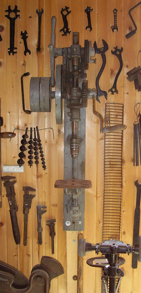
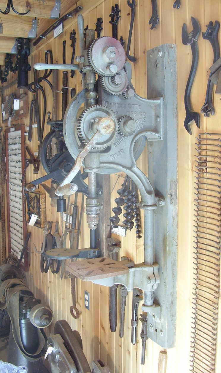
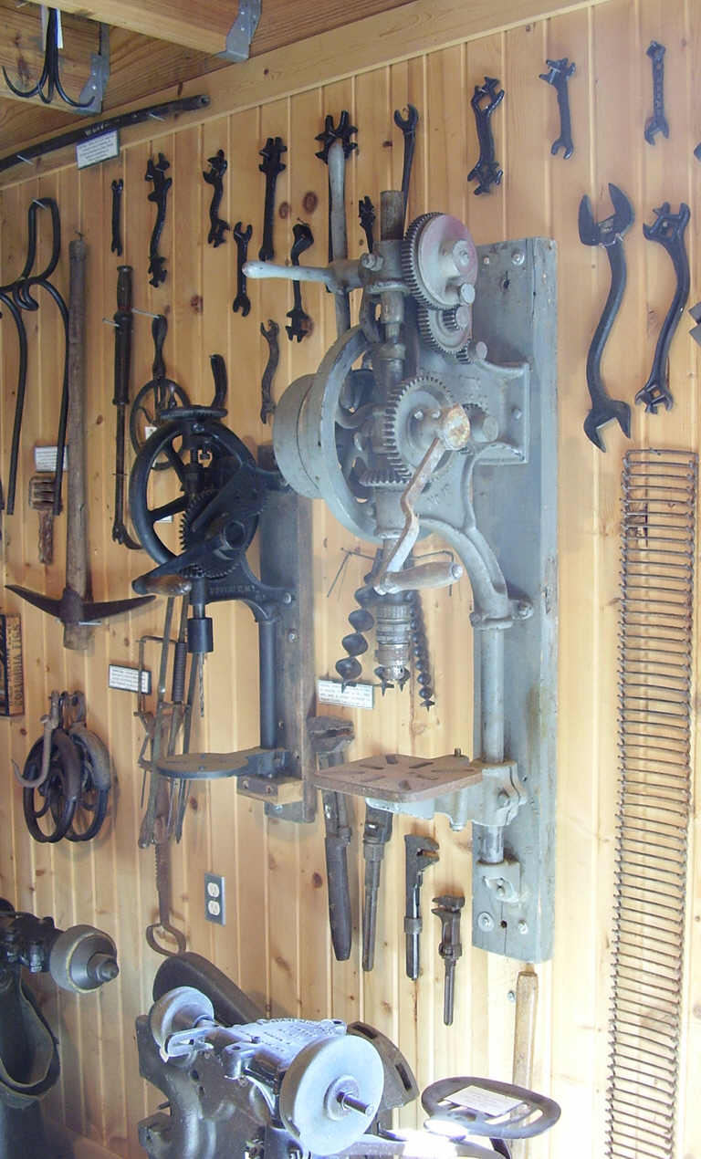
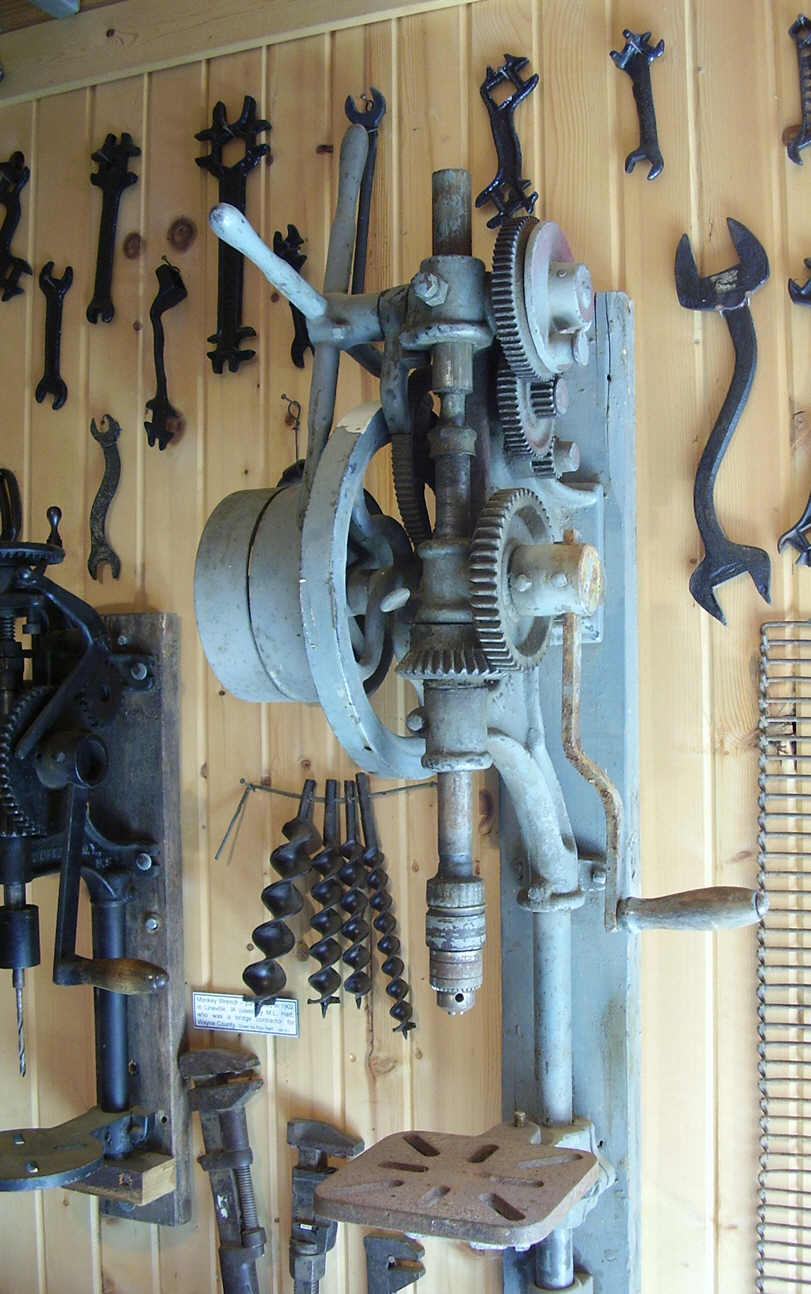 Auto-feed
wheel input. Auto-feed on the Number 19 is driven by a rocker arm that pivots
in its middle, the lower end of the rocker riding on an eccentric cam machined on
the top of the spindle gear, and the upper end of the rocker arm pushing and
advancing the auto-feed wheel by way of a small dog that is riveted to the upper
end of the arm. The upper half of the rocker arm can be seen in the large photo
(above left) extending above the top of the drill, in the middle of the drill
frame behind the auto-feed drive gears. The dog riveted to the top of the rocker
arm, is gravity loaded. The dog pushes against the teeth that are cut into the
auto-feed drive wheel, thus forcing the auto-feed wheel to turn. The dog pushes
only in one direction, and skips over the feed wheel teeth when the rocker returns
in the opposite direction. The rocker arm pivots on a bolt that is threaded into
the side of the drill frame. An eccentric cam lobe has been machined on the side
surface of the upper end of the spindle gear. The rocker arm has a foot machined
on its lower end - the foot reaches under the frame of the machine to ride on the
cam lobe on top of the spindle gear - between the spindle shaft and the front of
the drill frame. A small thumbscrew is threaded into the frame of the drill above
the spindle gear - the end of the thumb screw pressing against the foot on the
rocker arm. The thumbscrew limits the amount of travel that the rocker arm can
move. The thumbscrew is used to adjust the speed of the auto-feed mechanism by
limiting the travel of the rocker arm foot where it rides on the eccentric cam.
Using the thumbscrew, the auto-feed speed - that is, the amount of distance the
drill is forced into the work with each rotation of the drill - the auto-feed
rocker arm can be adjusted to move the feed wheel by 1-3 teeth with each rotation
of the drill. The 4-handled lever will rotate as the drill spindle is fed into the
work. There is no way to prevent this because the 4-handle feed lever is mounted
on the feed pinion shaft - it turns whenever the pinion gear is rotating and
lifting/raising the spindle. To engage or disengage the auto-feed, follow the
directions in the paragraph below named 'Using the 4-handled feed lever.'
Auto-feed
wheel input. Auto-feed on the Number 19 is driven by a rocker arm that pivots
in its middle, the lower end of the rocker riding on an eccentric cam machined on
the top of the spindle gear, and the upper end of the rocker arm pushing and
advancing the auto-feed wheel by way of a small dog that is riveted to the upper
end of the arm. The upper half of the rocker arm can be seen in the large photo
(above left) extending above the top of the drill, in the middle of the drill
frame behind the auto-feed drive gears. The dog riveted to the top of the rocker
arm, is gravity loaded. The dog pushes against the teeth that are cut into the
auto-feed drive wheel, thus forcing the auto-feed wheel to turn. The dog pushes
only in one direction, and skips over the feed wheel teeth when the rocker returns
in the opposite direction. The rocker arm pivots on a bolt that is threaded into
the side of the drill frame. An eccentric cam lobe has been machined on the side
surface of the upper end of the spindle gear. The rocker arm has a foot machined
on its lower end - the foot reaches under the frame of the machine to ride on the
cam lobe on top of the spindle gear - between the spindle shaft and the front of
the drill frame. A small thumbscrew is threaded into the frame of the drill above
the spindle gear - the end of the thumb screw pressing against the foot on the
rocker arm. The thumbscrew limits the amount of travel that the rocker arm can
move. The thumbscrew is used to adjust the speed of the auto-feed mechanism by
limiting the travel of the rocker arm foot where it rides on the eccentric cam.
Using the thumbscrew, the auto-feed speed - that is, the amount of distance the
drill is forced into the work with each rotation of the drill - the auto-feed
rocker arm can be adjusted to move the feed wheel by 1-3 teeth with each rotation
of the drill. The 4-handled lever will rotate as the drill spindle is fed into the
work. There is no way to prevent this because the 4-handle feed lever is mounted
on the feed pinion shaft - it turns whenever the pinion gear is rotating and
lifting/raising the spindle. To engage or disengage the auto-feed, follow the
directions in the paragraph below named 'Using the 4-handled feed lever.'

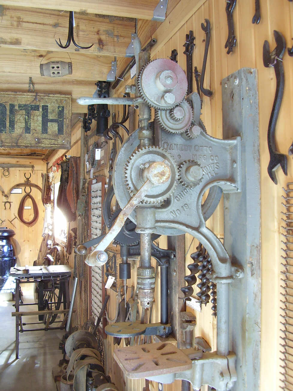
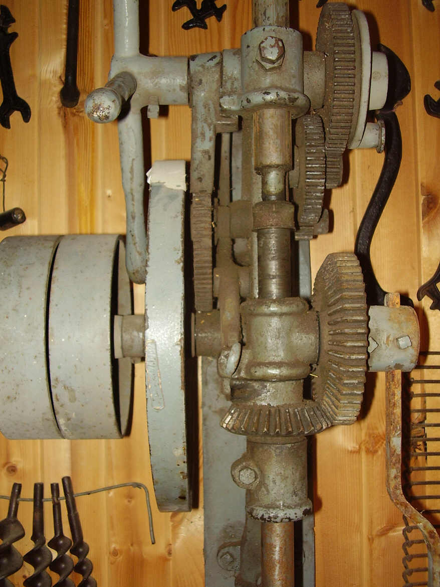
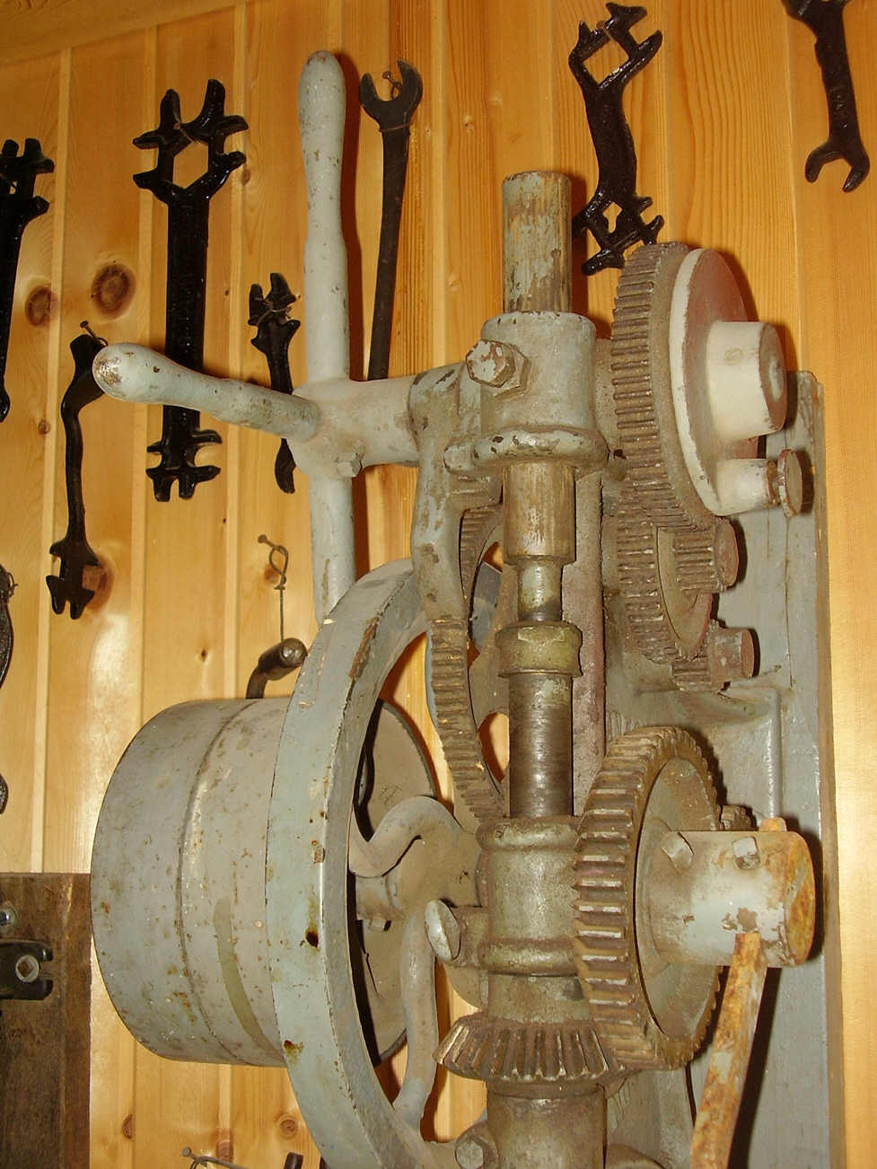 A
spring-loaded ratchet dog holds the feed wheel in place while the auto-feed is
returning back to its starting position. This ratchet dog is easy to see in two of
the photos (at near left). The ratchet dog is a short simple lever that is mounted
above the front of the feed wheel. The upper end of the dog is mounted on the
middle of the rack pinion shaft between the 4-handle lever and the drill frame.
The lower end of the dog is sharpened to a blunt flat edge that catches in the
teeth in the feed wheel. A little 'ear' is cast into the middle of the ratchet
arm. The ear extends under part of the drill frame where a small spring can push
against the ratchet dog. The spring applies pressure to the ratchet dog to keep it
continuously engaged in the feed wheel teeth - to prevent the feed wheel from
backing off pressure on the spindle while the auto-feed rocker arm is moving in
the opposite direction.
A
spring-loaded ratchet dog holds the feed wheel in place while the auto-feed is
returning back to its starting position. This ratchet dog is easy to see in two of
the photos (at near left). The ratchet dog is a short simple lever that is mounted
above the front of the feed wheel. The upper end of the dog is mounted on the
middle of the rack pinion shaft between the 4-handle lever and the drill frame.
The lower end of the dog is sharpened to a blunt flat edge that catches in the
teeth in the feed wheel. A little 'ear' is cast into the middle of the ratchet
arm. The ear extends under part of the drill frame where a small spring can push
against the ratchet dog. The spring applies pressure to the ratchet dog to keep it
continuously engaged in the feed wheel teeth - to prevent the feed wheel from
backing off pressure on the spindle while the auto-feed rocker arm is moving in
the opposite direction.
Using the 4-handled feed lever. This large lever is used exactly like the large multi-handled levers on modern drill presses. The feed lever will not move the drill feed until it is disengaged. The auto-feed is disengaged by pulling out, and rotating a spring-loaded pin that is located in the large auto-feed gear. See the large photo (above right). The knob mounted on the large auto-feed gear contains a spring-loaded pin. To disengage the pin, the knob is grasped and pulled out and rotated. A small stud inside the knob prevents the pin from re-seating after it is pulled out and rotated. This disengages the auto-feed mechanism. The 4-handled feed lever can now be used to quickly raise and lower the drill spindle. To re-engage the auto-feed, the knob on the auto-feed gear is simply rotated until the small stud inside the knob realigns with the corresponding relief hole in the gear plate, and the knob snaps back into place under spring tension. It may be necessary to grasp the 4-handled feed lever and rotate it until the knob and pin realign with the hole in the auto-feed gear. The spring loaded pin immediately snaps back into the hole when the pin and hole are re-aligned. With the auto-feed know pulled out to the open position, the entire auto-feed gear train was bypassed. With the auto-feed gear train bypassed, the large auto-feed gear is disconnected from the rack pinion shaft that it is mounted on - the shaft will spin freely inside the gear thus allowing free movement of the rack pinion shaft. The 4-handle feed lever is fixed to the opposite end of the rack pinion shaft, and the 4-handle can now be used to rotate the pinion shaft and thus run the drill spindle up or down.

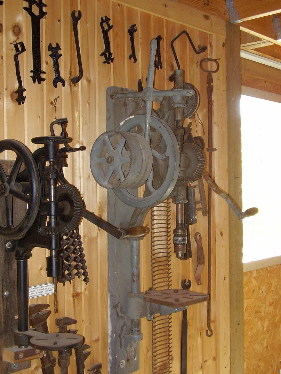

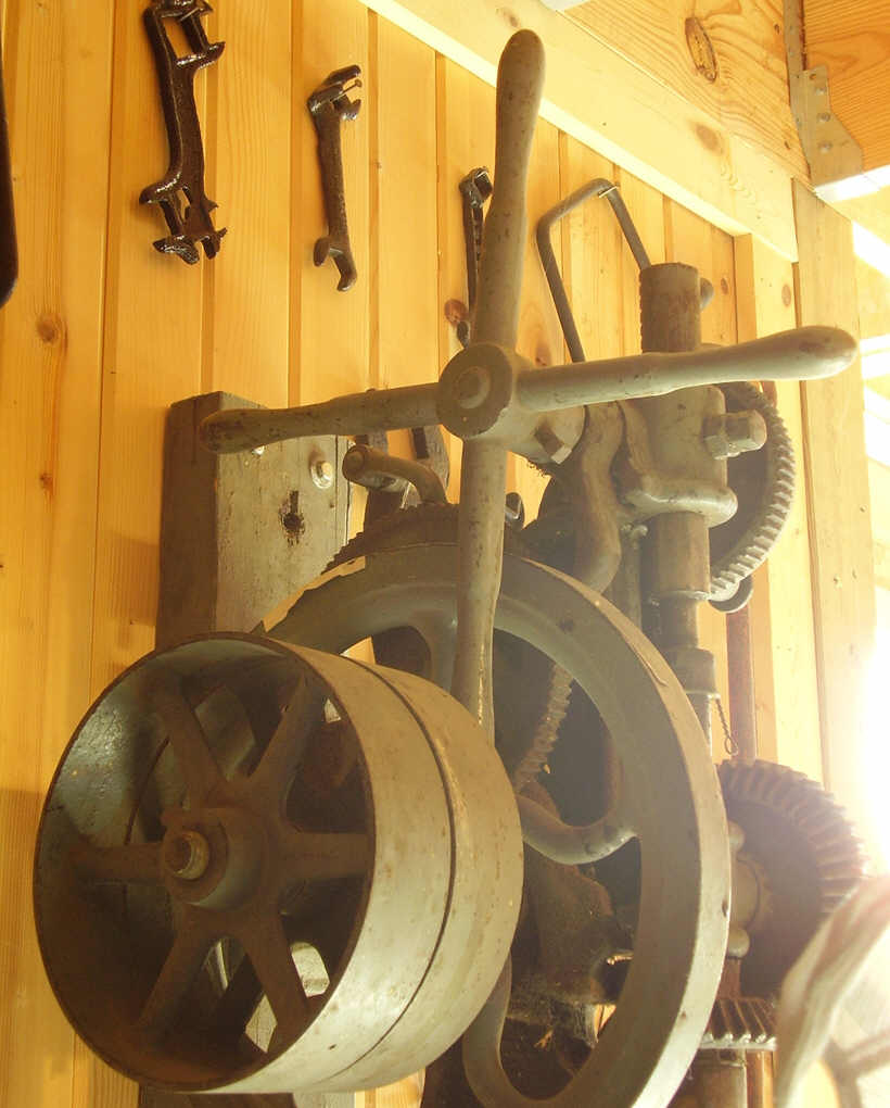 Free
and fixed pulleys were mounted on the flywheel shaft - next to the flywheel on
the left side of the machine. The outer pulley on this drill (fixed pulley) was
fixed to the flywheel shaft by tightening the set screw located in the center of
the pulley. The inner (free pulley) pulley was left loose so that it could rotate
freely without causing the flywheel shaft to turn. A shift lever would be used
with this drill to allow it to be powered by a flat belt and lineshaft. The lever
would have been a wrought iron bar with forks forged on one end to fit around the
lineshaft belt, and would have been used to move the rotating belt off of one
pulley and onto the other pulley. During idle periods when lineshaft belt was
running, the belt would have been shifted onto the free pulley - the free pulley
spinning with the lineshaft belt but not turning the drill. When it was desired to
operate the drill, the mechanic would pull the belt shifting lever, moving the
belt onto the fixed pulley, and started the drill turning under lineshaft power.
The catalog does not show a forked shifting lever for this drill, so the lever
might have been supplied by the owner of the drill.
Free
and fixed pulleys were mounted on the flywheel shaft - next to the flywheel on
the left side of the machine. The outer pulley on this drill (fixed pulley) was
fixed to the flywheel shaft by tightening the set screw located in the center of
the pulley. The inner (free pulley) pulley was left loose so that it could rotate
freely without causing the flywheel shaft to turn. A shift lever would be used
with this drill to allow it to be powered by a flat belt and lineshaft. The lever
would have been a wrought iron bar with forks forged on one end to fit around the
lineshaft belt, and would have been used to move the rotating belt off of one
pulley and onto the other pulley. During idle periods when lineshaft belt was
running, the belt would have been shifted onto the free pulley - the free pulley
spinning with the lineshaft belt but not turning the drill. When it was desired to
operate the drill, the mechanic would pull the belt shifting lever, moving the
belt onto the fixed pulley, and started the drill turning under lineshaft power.
The catalog does not show a forked shifting lever for this drill, so the lever
might have been supplied by the owner of the drill.
Rachet dog and spring are both visible in photos (near right). In the two photos (near right) the ratchet dog that prevents reversal of the feed wheel, is visible in the upper middle area of the photos. The ratchet dog is hung on the middle of the rack pinion shaft between the 4-handle feed lever and drill frame. The ratchet dog is slightly curved so that its pointed end will fit into the teeth of the feed wheel. Look closely at the photos, the middle of the curved ratchet dog passes closely near the upper journal of the drill frame, and a tiny spring is inserted between the ratchet dog and the rear edge of the upper journal. The small spring pushes the dog into the ratchet teeth in the feed wheel. This spring must be present in order for the auto-feed to function. If the spring is lost, then the auto-feed will not be able to force the drill into the work. However the 4-handled feed lever will still function even if the auto-feed is no longer available. The spring is easily replaced with new spring available at any machinery supplier today.
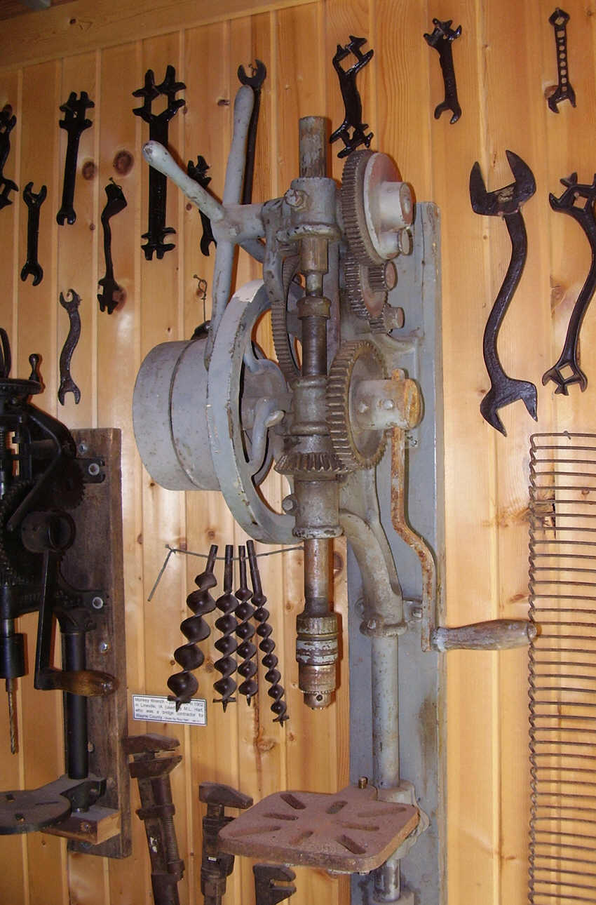
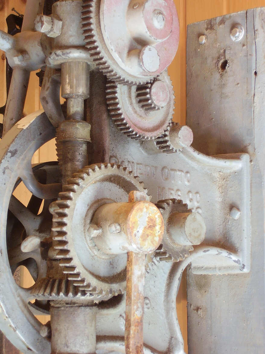
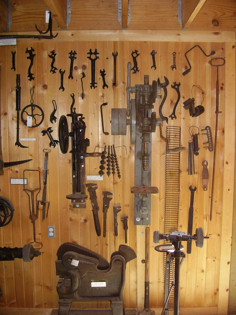
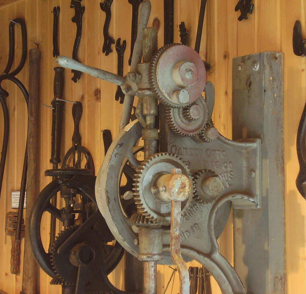 This
drill is in great shape. A small modern keyed chuck was installed in the Western
Chief Safety Chuck by the previous owner. The keyed chuck is mounted on a straight
shank arbor and installed in the original Western Chief Safety Chuck as though it
were just another straight shank drill bit. The keyed chuck allowed the use of
modern jobber type drill bits in this drill. The Canedy-Otto Number 19 post drill
was meant to be mounted to a post or column. The frame of this drill mounts too
closely to the wall to allow effective use of the hand crank. Mounting to a post
would allow clearance around the hand crank for best hand operation of the drill.
This
drill is in great shape. A small modern keyed chuck was installed in the Western
Chief Safety Chuck by the previous owner. The keyed chuck is mounted on a straight
shank arbor and installed in the original Western Chief Safety Chuck as though it
were just another straight shank drill bit. The keyed chuck allowed the use of
modern jobber type drill bits in this drill. The Canedy-Otto Number 19 post drill
was meant to be mounted to a post or column. The frame of this drill mounts too
closely to the wall to allow effective use of the hand crank. Mounting to a post
would allow clearance around the hand crank for best hand operation of the drill.
Where
to see this drill: Prairie Trails Museum of Wayne Country. Highway 2 East,
P.O. Box 104, Corydon, Iowa, USA.
www.prairietrailsmuseum.org Located on highway 2. Look for the red barn with
the steam traction engine in front. The main museum building contains displays of
early American life during the late 1800s and early 1900s. The barn is filled with
wagons and farm implements and machinery from this same time period.
Champion No. 7 Post Drill. Manufactured by Champion Blower & Forge Company. This drill appears in their 1909 catalog as Number 7 Champion Improved Back Geared Automatic Self-Feed Post Drill. The No.7 is a high quality two-speed post drill made with ball bearings. Speed changes are made by unlatching and shifting the double back gear to engage the proper gears for desired speed and torque. High speed low torqure for faster drilling with smaller drill bits, and low speed high torque for drilling with larger drill bits. The No.7 could be ordered with or without the optional fixed and free pulleys for lineshaft use as desired.
The No. 7 is a 21-inch drill with a vertical run of 5-1/2 inches, and will bore holes up to 1-1/2 inches diameter. The chuck was bored for 41/64ths inch straight shank bits but could also be special ordered with 1/2-inch straight shank drill chucks. 5/8ths inch straight shank bits will fit 41/64ths bores. 5/8-inch equals 40/64ths inch.

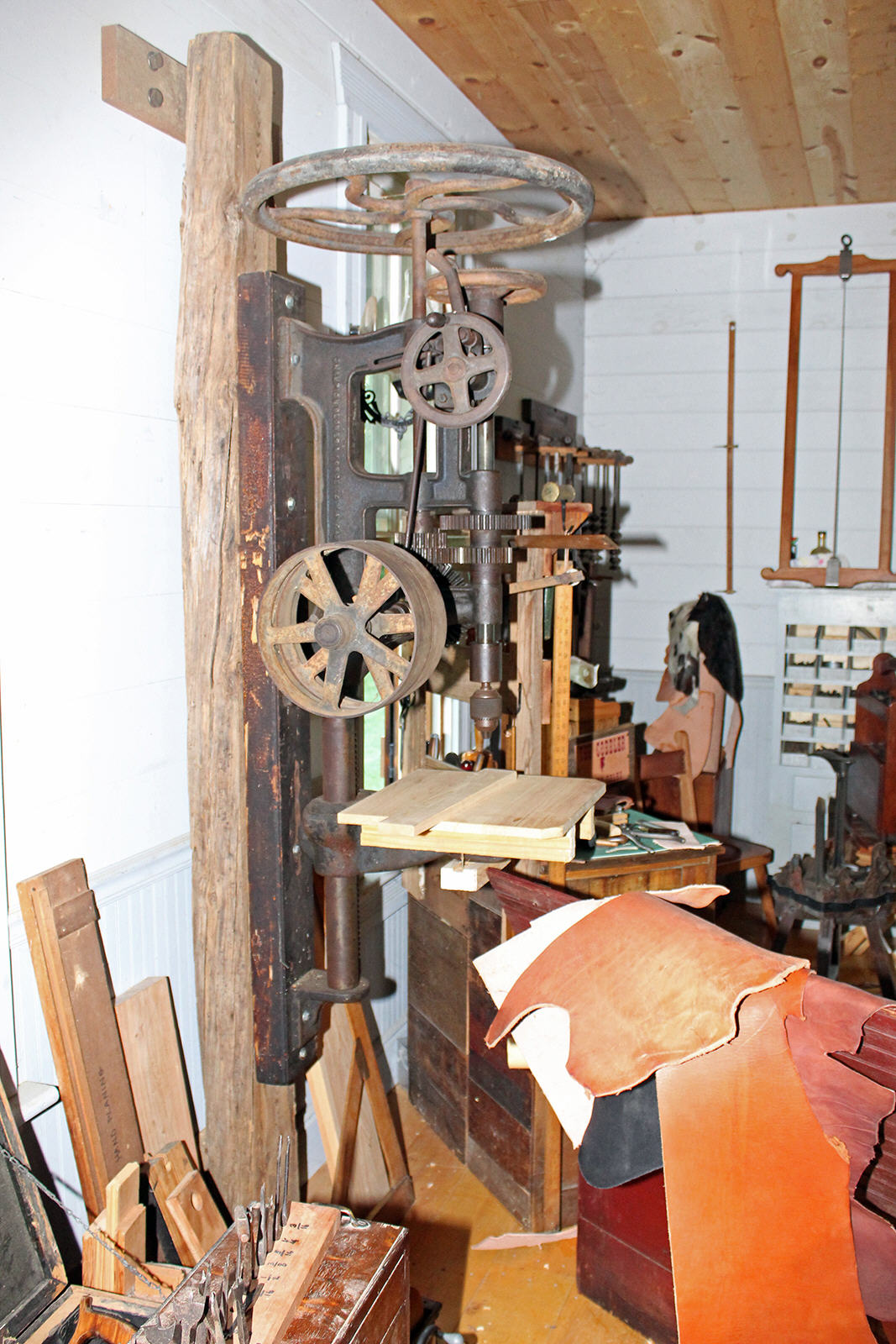
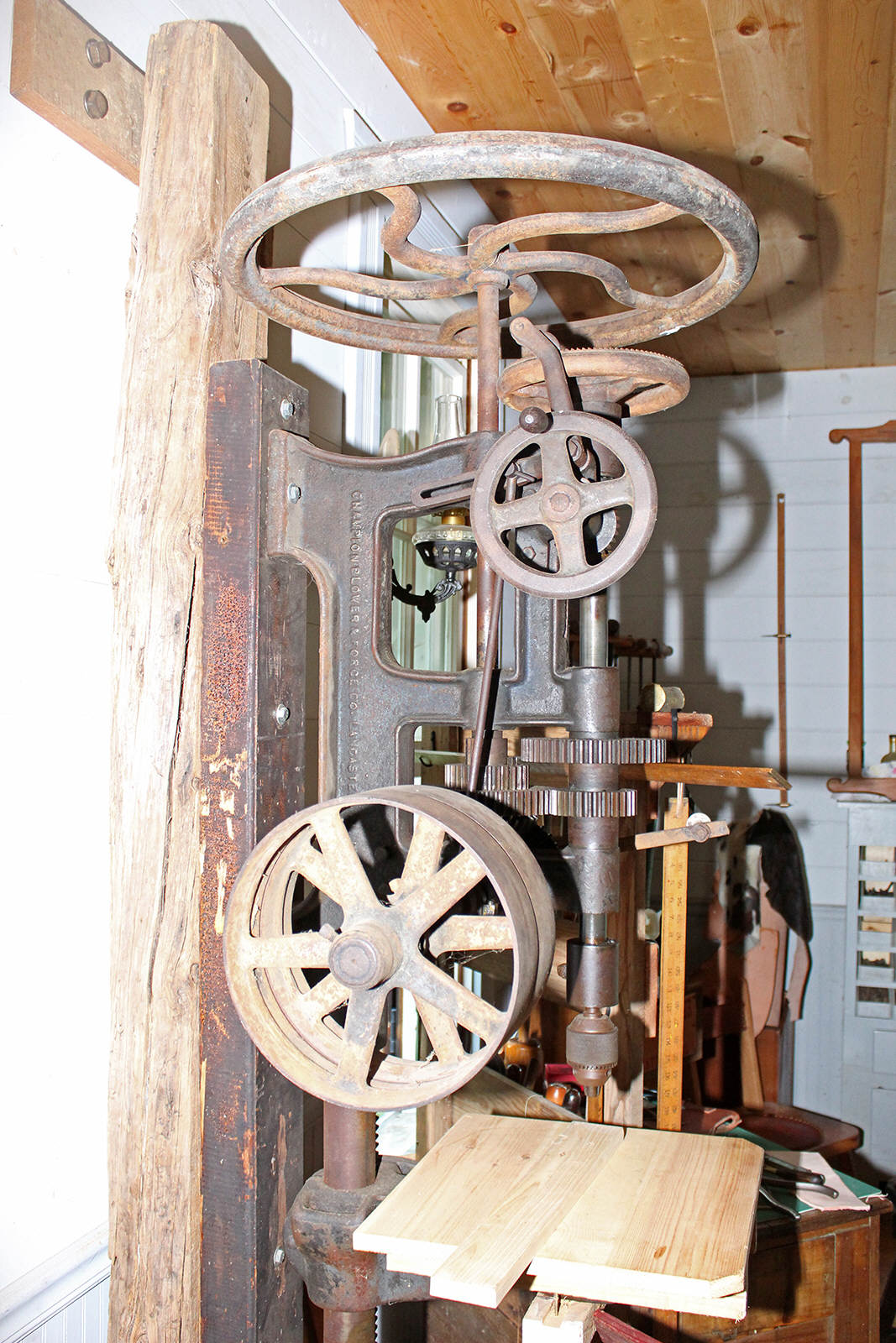
The drill table support arm has a rack and pinion gear for easy raising and lowering of the drill table. The rack is mounted through the table support arm and the pinion gear is mounted inside the table support arm. The rack rotates freely around the table post simultaneously with the support arm when the arm is swung/repositioned from side to side.
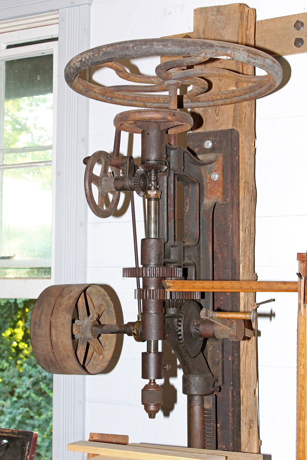
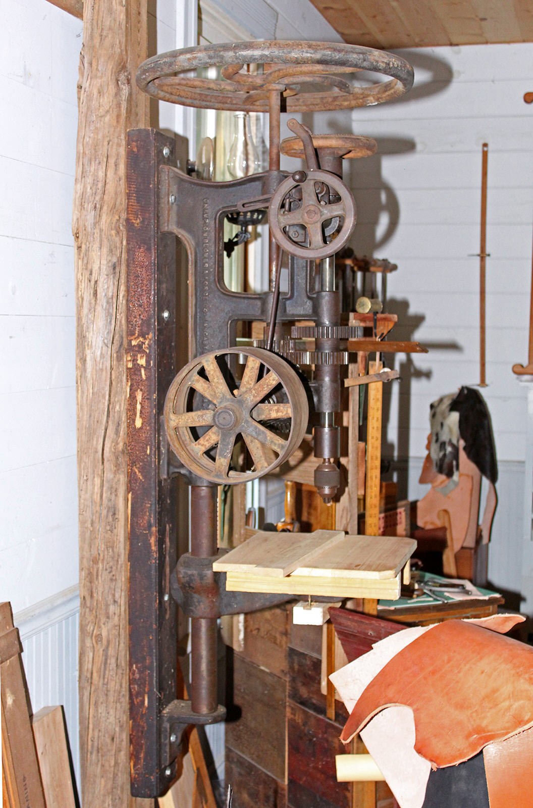
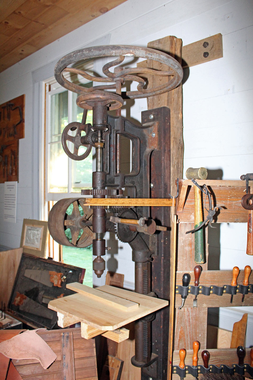 Weight is 400lbs. without lineshaft pulleys, or 425lbs. with
lineshaft pulleys. This is a big drill. I estimate that the drill by itself is
roughly 6' tall. Mounted to the wall as shown in the photos here, a foot or so
above the shop floor - the top of this drill is over 7 feet above the floor! And
the vertical overhead flywheel moves that great big flywheel up out of the way
and greatly increases and improves workspace around the drill.
Weight is 400lbs. without lineshaft pulleys, or 425lbs. with
lineshaft pulleys. This is a big drill. I estimate that the drill by itself is
roughly 6' tall. Mounted to the wall as shown in the photos here, a foot or so
above the shop floor - the top of this drill is over 7 feet above the floor! And
the vertical overhead flywheel moves that great big flywheel up out of the way
and greatly increases and improves workspace around the drill.
In 1909 this drill cost $40 for the basic drill and $44 for the drill with free and fixed pulleys. My oh my how the U.S. government and the central banks have inflated our paper money into near worthlessness.
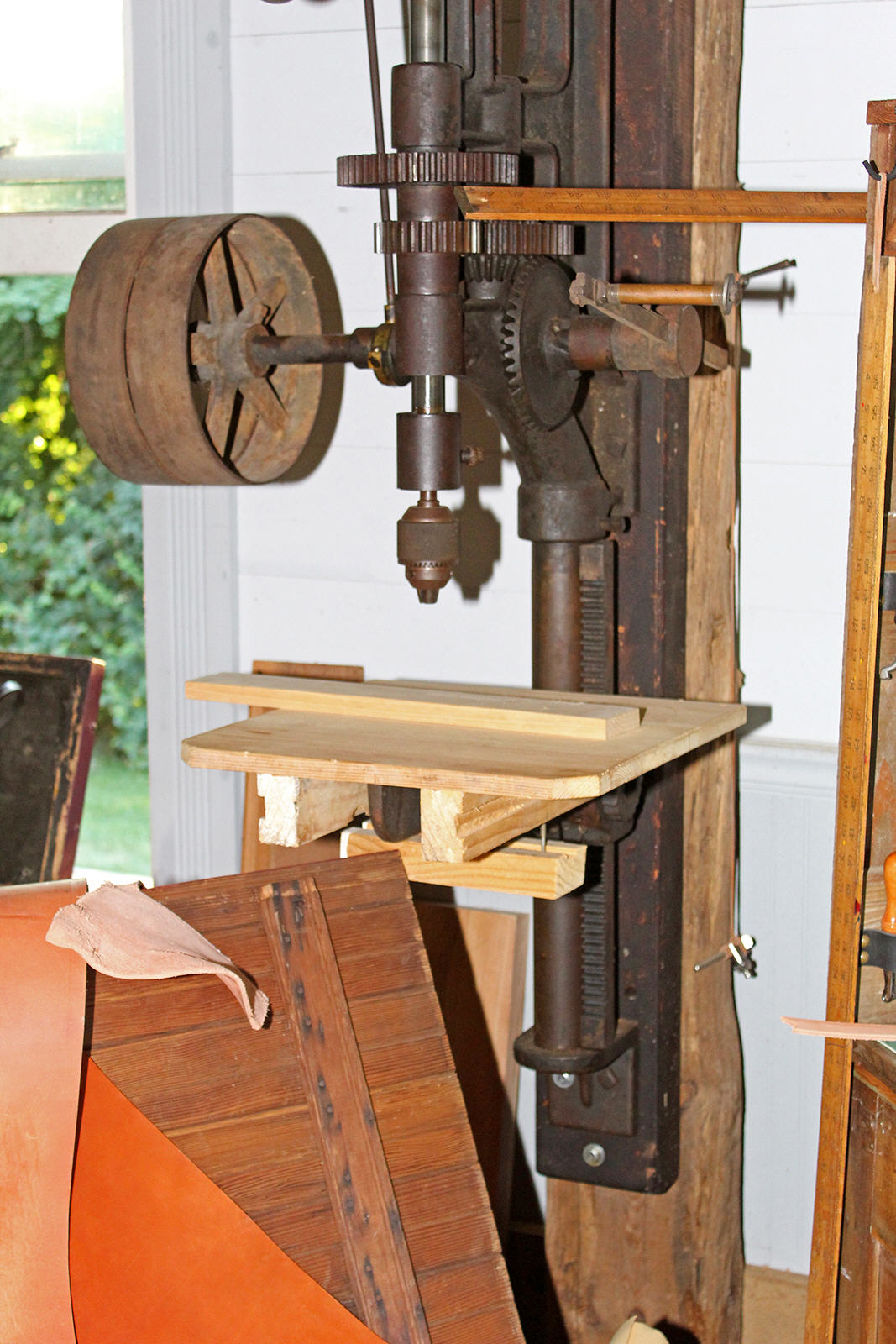 R
R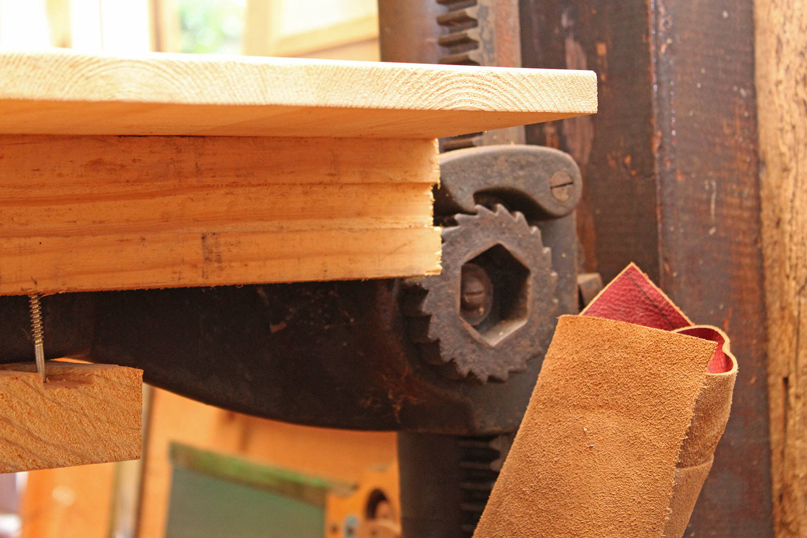
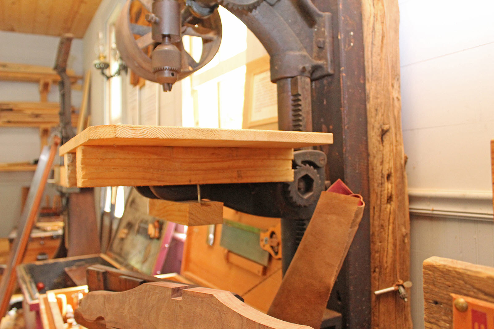 aising and lowering the drill table. Raising
and lowering the heavy drill table and support arm was made easy by use of a
rack and pinion gear. A crank handle was fitted to the pinion gear for this
purpose. The crank handle gives the user leverage for overcoming friction and
lifting the heavy table and thus makes task simple and not unpleasant. The table
crank handle is mounted to a ratchet wheel (looks like a gear) to make adjusting
table height easier. The ratchet wheel and pawl are on the outside of the table
arm, and the pinion gear is on the inside. If the mechanic were to let go of the
crank handle before the support arm is tightened to the post, then the table
would slide all the way back down to the bottom of its travel before the
mechanic could get a wrench on the rear tension bolts. The ratchet pawl catches
the downward rotation of the ratchet wheel and holds it in place so that the
mechanic has both hands free to tighten tension bolts on the back of the table
arm. To lower the table, the mechanic flips the ratchet pawl backwards and then
the ratchet wheel will rotate freely in the downward direction of rotation.
Simply flip the pawl back into the ratchet wheel teeth, and the table crank is
ready for raising the height again.
aising and lowering the drill table. Raising
and lowering the heavy drill table and support arm was made easy by use of a
rack and pinion gear. A crank handle was fitted to the pinion gear for this
purpose. The crank handle gives the user leverage for overcoming friction and
lifting the heavy table and thus makes task simple and not unpleasant. The table
crank handle is mounted to a ratchet wheel (looks like a gear) to make adjusting
table height easier. The ratchet wheel and pawl are on the outside of the table
arm, and the pinion gear is on the inside. If the mechanic were to let go of the
crank handle before the support arm is tightened to the post, then the table
would slide all the way back down to the bottom of its travel before the
mechanic could get a wrench on the rear tension bolts. The ratchet pawl catches
the downward rotation of the ratchet wheel and holds it in place so that the
mechanic has both hands free to tighten tension bolts on the back of the table
arm. To lower the table, the mechanic flips the ratchet pawl backwards and then
the ratchet wheel will rotate freely in the downward direction of rotation.
Simply flip the pawl back into the ratchet wheel teeth, and the table crank is
ready for raising the height again.
The rack is installed through the inside of the drill table support arm and is held in place by the arm against the post. There are no other parts attaching the rack to the post. The rack slides freely with the arm bracket around the table post when the table is swung around on the post. Bottom of rack rests on the bottom post support mounting bracket to carry the weight of the table and arm. Keeping the entire table post clean insures easy movement of the rack and table support arm.

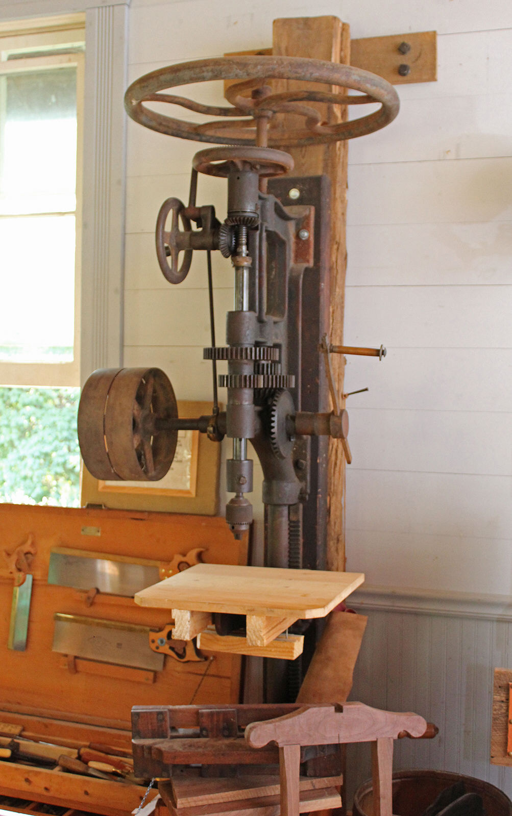
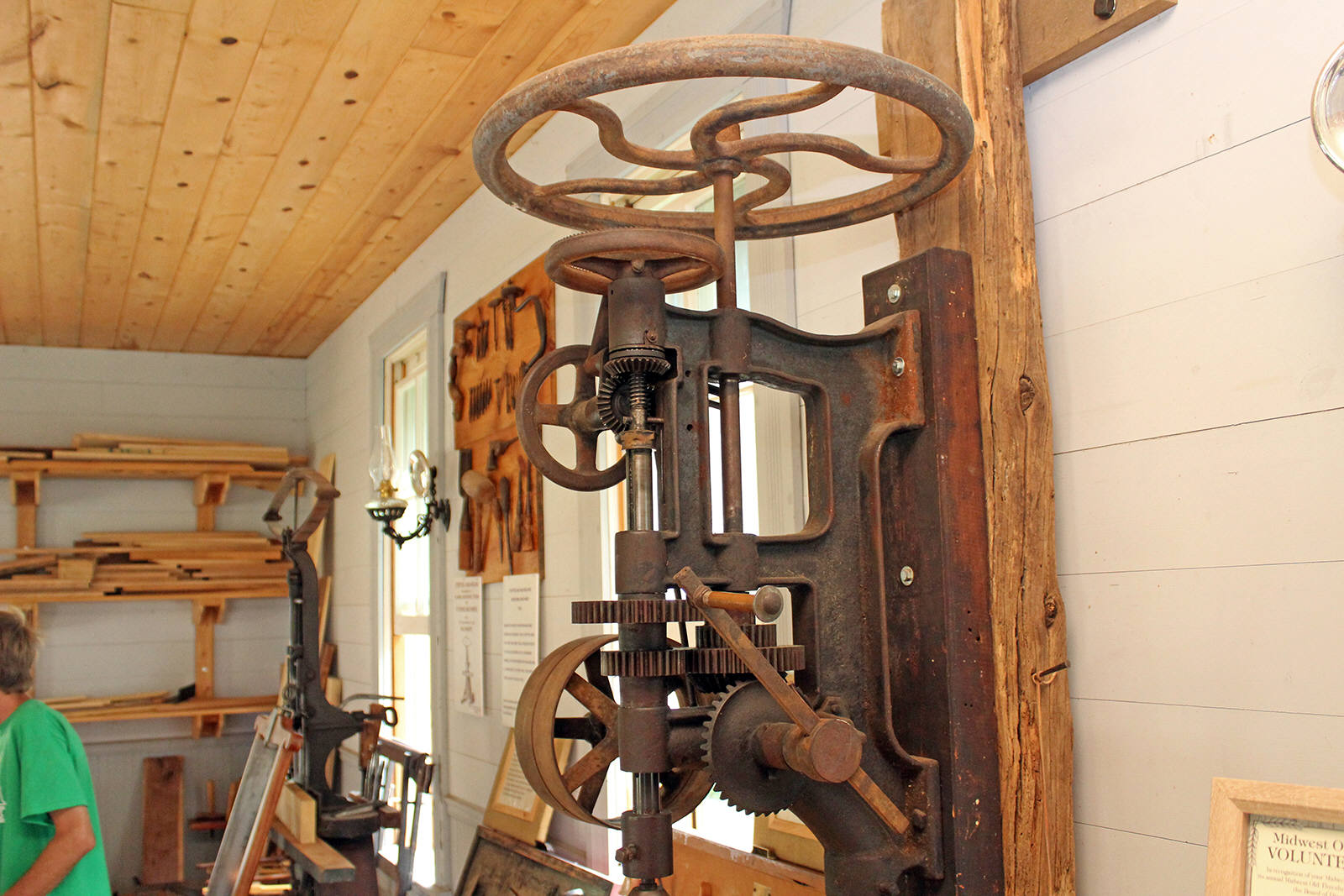 How to tell the No. 7 apart from the No. 999:
The Champion No. 7 and the Champion No. 999 look almost identical in the catalog.
The No. 7 is a 21-inch drill and the No. 999 is a 16-inch drill. This is measured from the center of the drill bit or chuck to the front surface of the drill table mounting post.
The No. 7 has a vertical rack and pinion for easy raising and lowering of the drilling table. The No. 999 does not have a rack and pinion.
Both the No. 7 and the No. 999 could be ordered with the same drill chucks and therefore identifying the chuck size on the drill will NOT indicate the model series of the drill. The standard size chuck bore for the No. 7 was 41/64ths-inch but this drill could be ordered with a 1/2-inch chuck bore. And the standard size chuck bore for the No. 999 was 1/2-inch but the No. 999 could be special ordered with a 41/64ths-inch chuck bore. Thus measuring the chuck bore is not an indication of which drill you might have. Also both drills could be ordered with or without fixed and free pulleys for lineshaft use. Use the two bulleted characteristics above to identify these two drills.
A separate wheel hanger bracket is provided for drilling wagon tires. To install the wheel hanger, the drill table arm is loosened and swung to the side and the hooked "T" end of the wheel hanger bracket is hung from notches on the support arm.
 Where to see this drill.
Located in the M. Dodd's Wood Shop, in the Log Village
on the south side of Midwest Old Thresher's, McMillan Park, Mount Pleasant, Iowa. Old Thresher's Reunion maintains a website at
http://www.oldthreshers.org/.
Where to see this drill.
Located in the M. Dodd's Wood Shop, in the Log Village
on the south side of Midwest Old Thresher's, McMillan Park, Mount Pleasant, Iowa. Old Thresher's Reunion maintains a website at
http://www.oldthreshers.org/.
COMMENT: October 12, 2021. I'm sorry about the stuff that is in front of the drill in many of these photos. This photo shoot was not planned, it was an unexpected surprise when I found it. I had no idea that I would find an almost (and in working condition) complete No.7 here. And it was the end of the day and getting dark fast so there wasn't time to improve the photo shoot. There were too many obstructions in front of the right side of the drill, so I could not get good photos, like for instance the antique wooden yardstick that extends in front of the drill and blocks part of the photos. In 2022 I re-visited and this location and
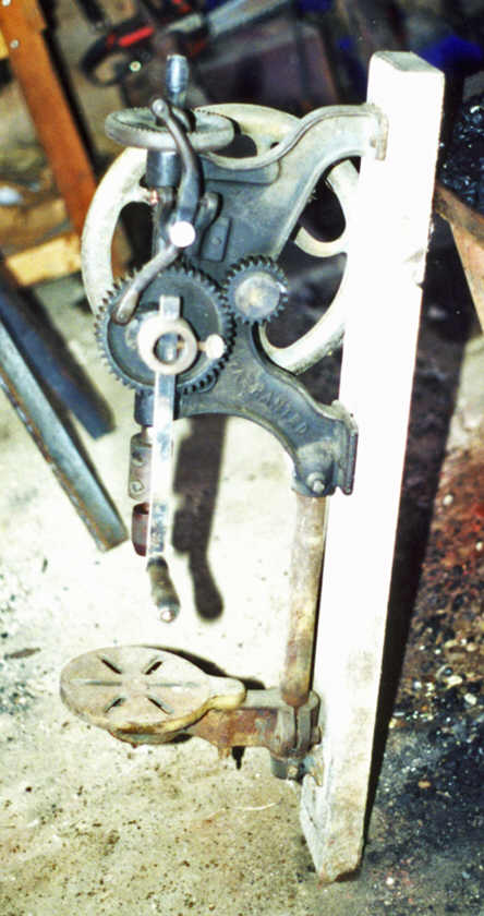
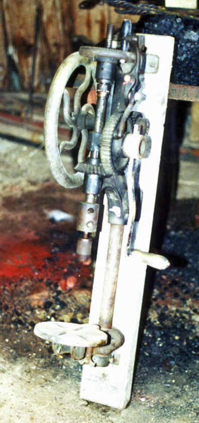
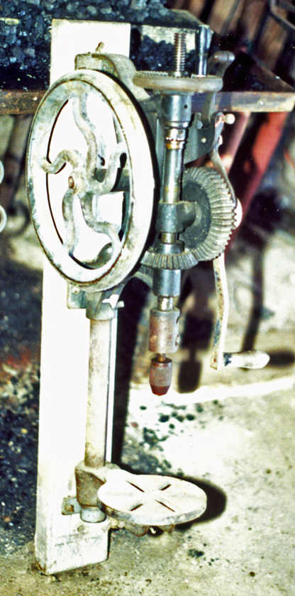
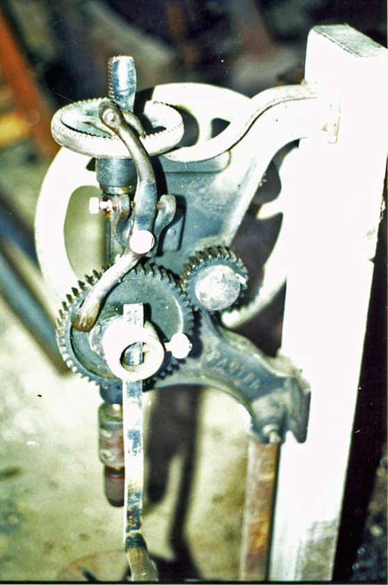
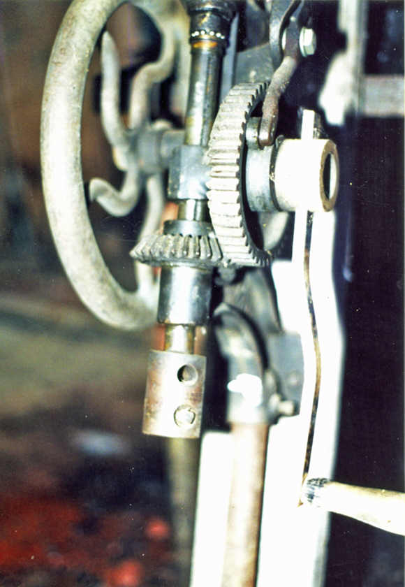 Champion No. 98 Post Drill. (Photos at
left) The Champion Blower & Forge Company Number 98 post drill is one of
Champion's smaller models and was designed for farmer's home workshops. The #98 is
a single speed drill, self-feed, rated for drilling holes up to 1 inch diameter,
length of vertical feed travel is 3 inches. The #98 will drill to the center of a
14-inch circle, thus making it a 7-inch drill press. Crank handle length is
adjustable. The #98 accepts 1/2-inch straight shank drill bits and was also
available by special order for use with 41/64-inch drill bits..
Champion No. 98 Post Drill. (Photos at
left) The Champion Blower & Forge Company Number 98 post drill is one of
Champion's smaller models and was designed for farmer's home workshops. The #98 is
a single speed drill, self-feed, rated for drilling holes up to 1 inch diameter,
length of vertical feed travel is 3 inches. The #98 will drill to the center of a
14-inch circle, thus making it a 7-inch drill press. Crank handle length is
adjustable. The #98 accepts 1/2-inch straight shank drill bits and was also
available by special order for use with 41/64-inch drill bits..
About this drill:About this drill: This drill is owned by the author. It was purchased for $65 at an antique tractor swap meet around 1999. More photos will be added later after this drill has been set up in the author's shop. The drill was in good working condition and was complete, no missing parts except for the chuck wrench. This drill appears to be an early model that was made before the introduction of the Champion Never-Slip Chuck. The chuck that was mounted on the author's post drill is a simple screw chuck that is identical to the red drill featured at top of this page. The chuck was in poor condition - the threads of the set screw hole were stripped out and the original set screw lost. The author re-threaded the set screw hole to a larger size and installed a cap screw temporarily in place of a suitable set screw.
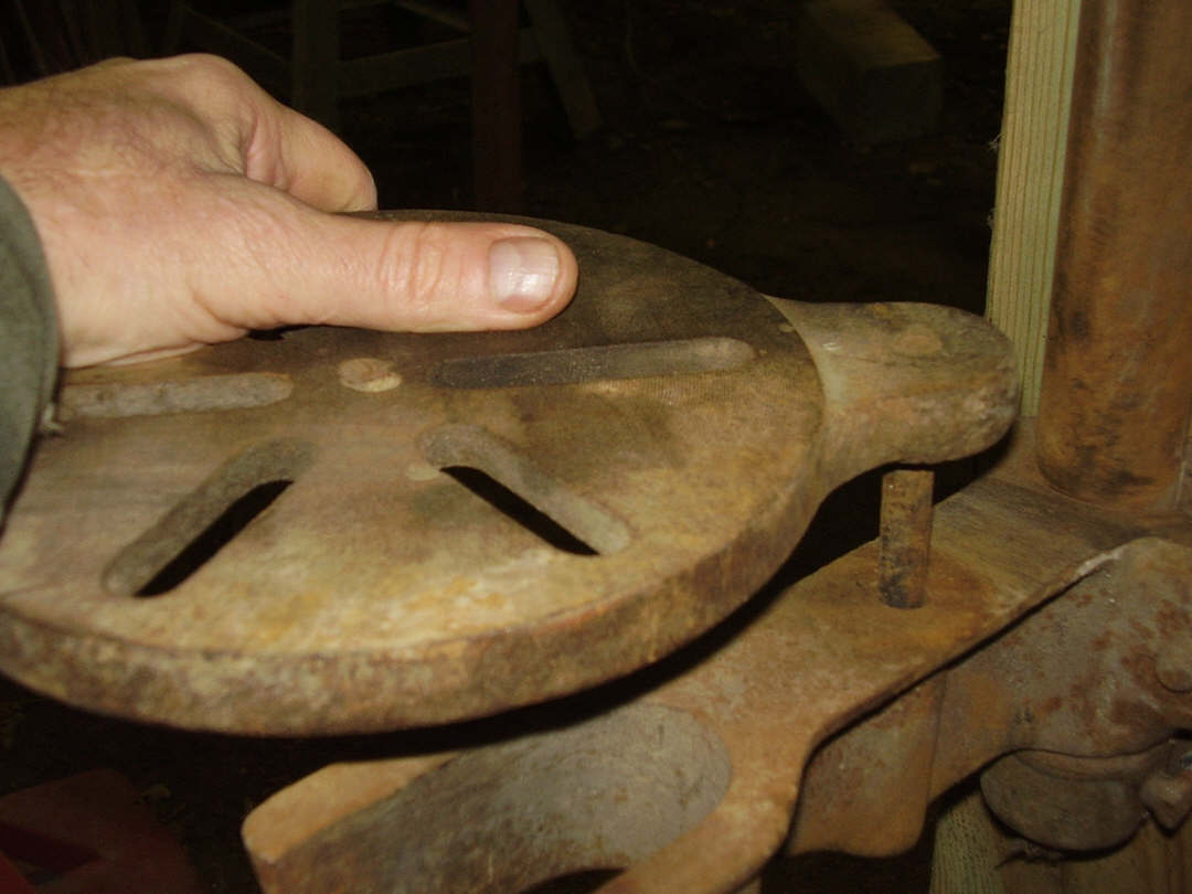
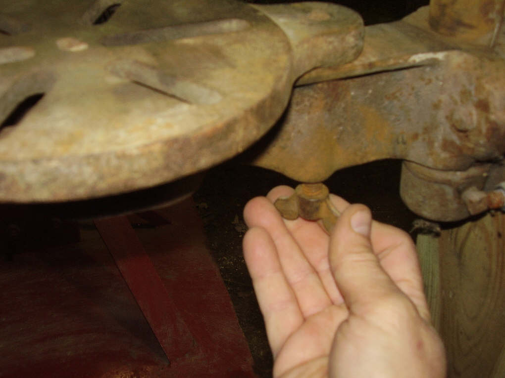
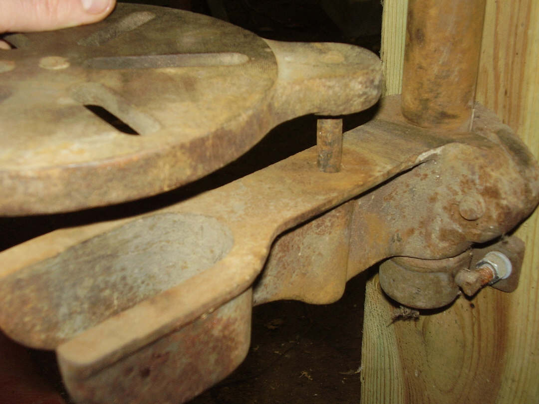
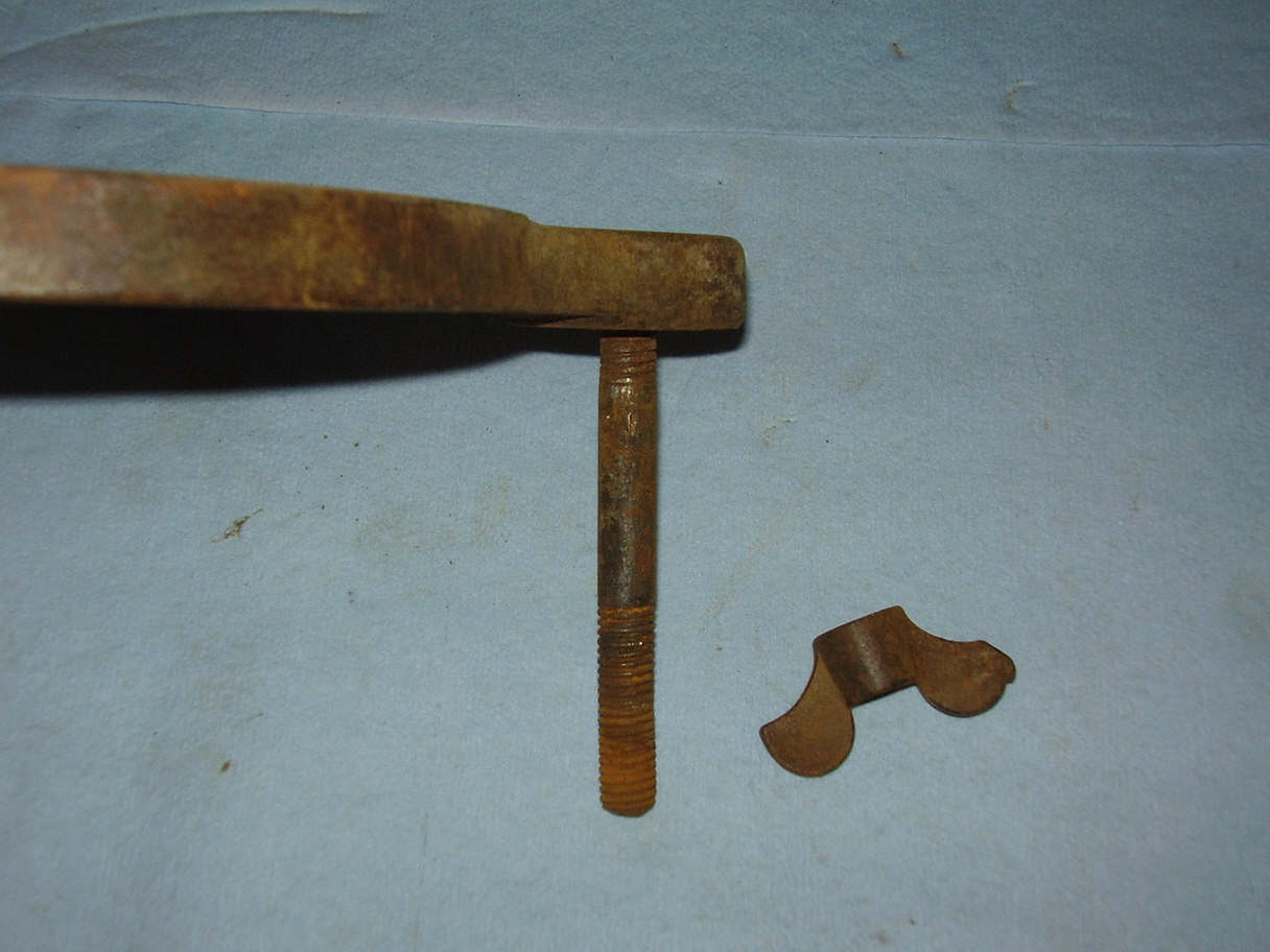

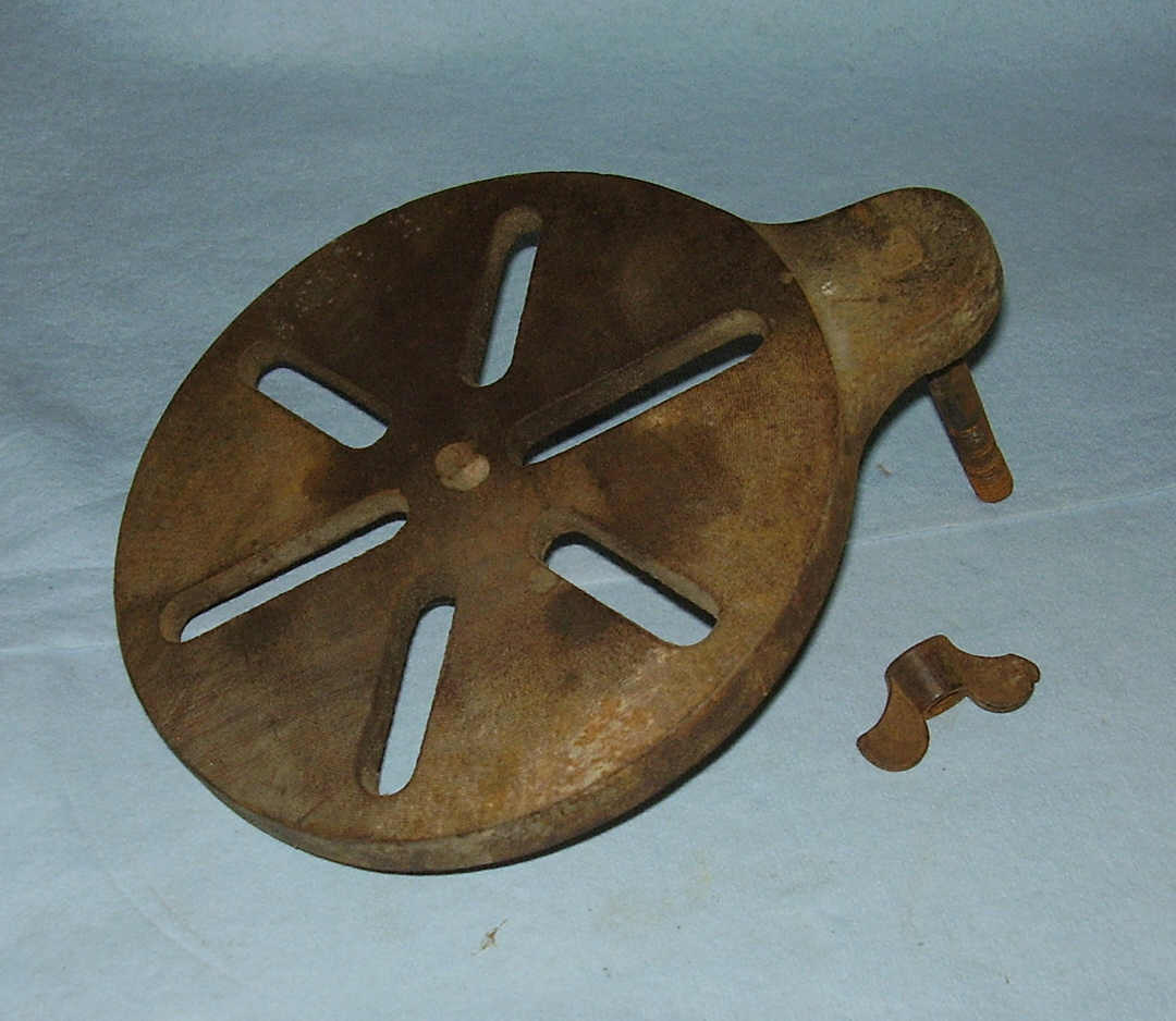 Table
and table rest assemble. The table is fastened to the table rest with a
single stud and wing-nut. The screw is actually a stud similar to those used to
fasten engine cylinder heads to engine blocks. A short and very coarse thread
size on one end threaded securely into the lobe on the drill press table, the
opposite end threaded with regular coarse threads for the wing-nut. The stud is
threaded tightly into the table lobe and does not turn. In the photos, the
author hand is seen lifting and rotating the drill table. The stud is fixed
immovably in the table lobe but can turn easily in the table support arm to
allow table to be swung to the side. Table can be loosened and swiveled to the
side to allow drilling wagon tires. The table support can be raised or lowered
on the table support shaft and tightened in place with the single table support
clamping screw. Photos at right show the table wing-nut removed to allow the
table to be removed.
Table
and table rest assemble. The table is fastened to the table rest with a
single stud and wing-nut. The screw is actually a stud similar to those used to
fasten engine cylinder heads to engine blocks. A short and very coarse thread
size on one end threaded securely into the lobe on the drill press table, the
opposite end threaded with regular coarse threads for the wing-nut. The stud is
threaded tightly into the table lobe and does not turn. In the photos, the
author hand is seen lifting and rotating the drill table. The stud is fixed
immovably in the table lobe but can turn easily in the table support arm to
allow table to be swung to the side. Table can be loosened and swiveled to the
side to allow drilling wagon tires. The table support can be raised or lowered
on the table support shaft and tightened in place with the single table support
clamping screw. Photos at right show the table wing-nut removed to allow the
table to be removed.
Feed arm & drive gear. The feed arm of the #98 is held against the eccentric wheel by spring pressure. The spring is installed in the frame near the feed arm pivot bolt. Another bolt on the feed arm frame (on the front side of the feed arm opposite of the spring) provides limited adjustment of the self-feed. A wheel is riveted to the lower end of the feed arm where it rides against the eccentric wheel. The eccentric wheel is built into the hub of the drive gear on this drill.


 Champion
No. 200 Post Drill. The Champion #200 is a medium size heavy
duty post drill that was rated to drill a 1 1/4-inch diameter hole and could drill
to the center of a 16-inch circle (8-inch drill press). The #200 was designed
specifically for the small professional blacksmith shop. Vertical feed pressure is
transmitted to the quill through ball bearings to reduce friction. This drill had
two feed options, self-feed, and lever feed. Changing between each feed option
took only a couple seconds. This fast-change dual feed option cut work time
dramatically by allowing the blacksmith to raise the drill up out of the work by
lever instead of unwinding the feed wheel, and the blacksmith also had the option
of using the lever feed for faster drilling in light work. The Champion #200
is a two-speed drill and the crank is turned in the same direction at both speed
settings. The #200 drill was bored for 1/2-inch straight shank drill bits, but
could be special ordered for 5/8-inch or 41/64-inch straight shank drill bits.
Drive and free pulley sets could also be special ordered to allow this drill to
run on line-shaft power in the shop. Author's note - this is an excellent drill. A
medium size drill with most of the options normally found on the largest drills.
To see photos of the blacksmith's shop where this drill is located, visit these
links: Steam Show
Blacksmith and
http://www.beautifuliron.com/cf_OldThreshersReunion.htm
Champion
No. 200 Post Drill. The Champion #200 is a medium size heavy
duty post drill that was rated to drill a 1 1/4-inch diameter hole and could drill
to the center of a 16-inch circle (8-inch drill press). The #200 was designed
specifically for the small professional blacksmith shop. Vertical feed pressure is
transmitted to the quill through ball bearings to reduce friction. This drill had
two feed options, self-feed, and lever feed. Changing between each feed option
took only a couple seconds. This fast-change dual feed option cut work time
dramatically by allowing the blacksmith to raise the drill up out of the work by
lever instead of unwinding the feed wheel, and the blacksmith also had the option
of using the lever feed for faster drilling in light work. The Champion #200
is a two-speed drill and the crank is turned in the same direction at both speed
settings. The #200 drill was bored for 1/2-inch straight shank drill bits, but
could be special ordered for 5/8-inch or 41/64-inch straight shank drill bits.
Drive and free pulley sets could also be special ordered to allow this drill to
run on line-shaft power in the shop. Author's note - this is an excellent drill. A
medium size drill with most of the options normally found on the largest drills.
To see photos of the blacksmith's shop where this drill is located, visit these
links: Steam Show
Blacksmith and
http://www.beautifuliron.com/cf_OldThreshersReunion.htm
The Number 200 drill shown here is mounted on a wall of a blacksmith's shop. It is in beautiful condition and appears to be complete (no parts missing). The blacksmith/owner uses this drill every day. A wood block has been placed on the drill table by the smith for drilling small objects. The #200 shows up in Champion's 1909 catalog so I estimate the age of this drill is probably around 100 years old.
Where to see this drill: Old Thresher's Reunion grounds, Mt. Pleasant, Iowa, USA. The drill featured here, is privately owned, and can be seen at the blacksmith shop in the North Village.
Old Threshers Reunion in Mount Pleasant, Iowa, USA, is a very large antique steam power and steam tractor show held once each year. Visitors to Old Threshers' will find a steam tractors, steam locomotives, agricultural equipment, and steam power industrial machinery in operation throughout the entire event. Visitors can ride on the restored steam trains and electric trolleys. Flea markets offer antique and modern tools for sale. To learn more about Old Threshers' Reunion go here: http://www.oldthreshers.org/

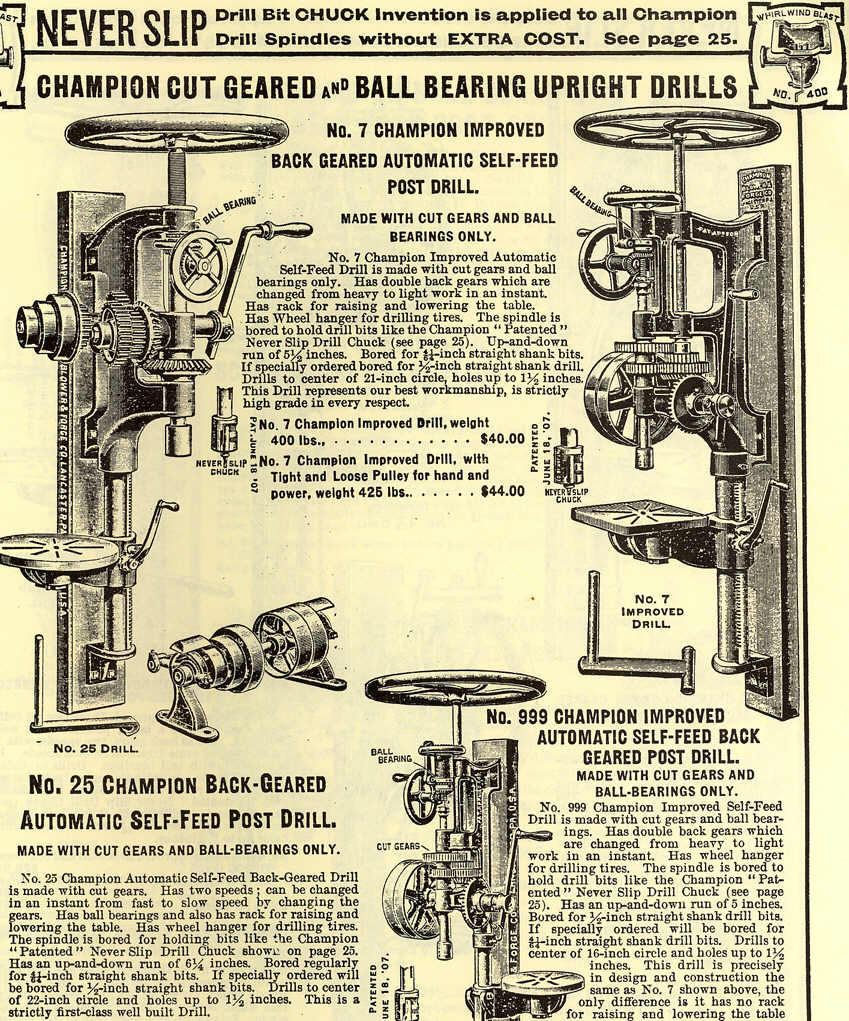
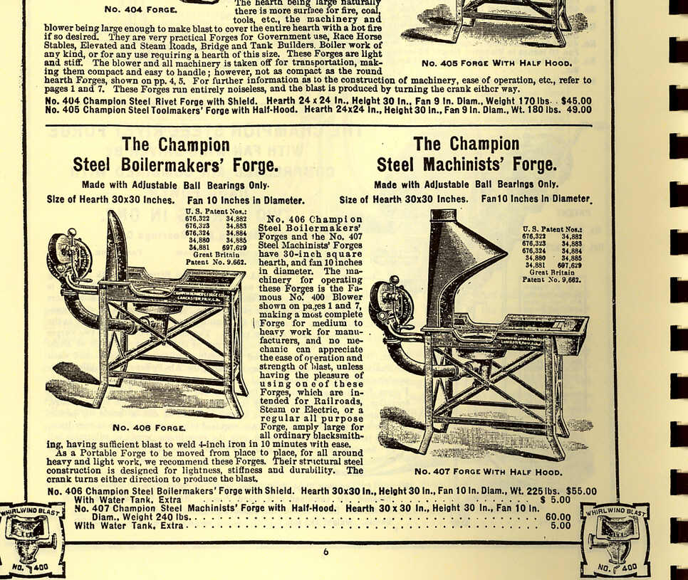
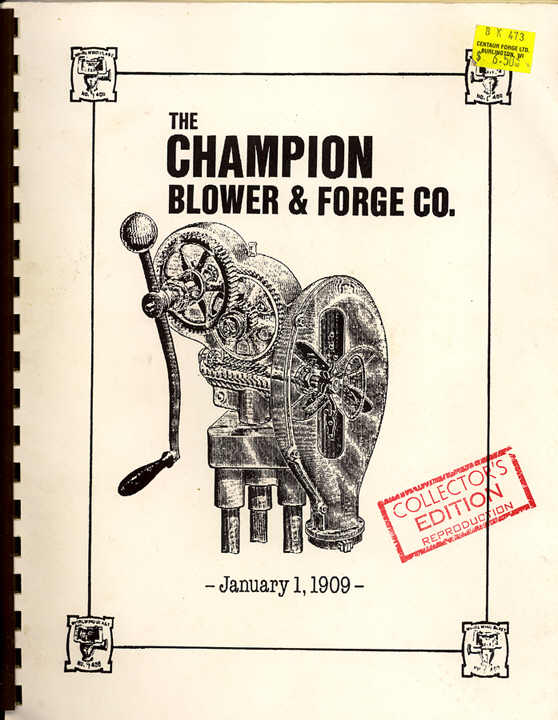 Champion
Blower & Forge Company Catalog 1909 reprint. For anyone interested in Champion
Blower & Forge Company products, I recommend buying a reprint of The Champion
Blower & Forge Company Catalog circa January 1909. Reprints of this catalog
can be purchased from Centaur Forge
http://www.centaurforge.com/ in their Metalworking Reference Materials
Book selection:
http://www.centaurforge.com/Metalworking-Reference-Materials/products/260/ , Burlington, Wisconsin, USA. The catalog shows
all of the company's products that were made in 1909. Drills, forges, blowers,
tire bending and shrinking equipment, taps and dies. This is an excellent source
featuring some of the best tools of the era. The catalog includes a cutaway
drawing of the internal working parts of the Champion 400 blower - the best hand
cranked ball-bearing forge blower ever made! The Champion Blower & Forge catalog of 1909 is an
excellent reference for identifying and inspecting these old tools and all of
their parts. Champion made some of the very best tools and these tools are still
used in many blacksmith, horseshoeing, and repair shops today.
Champion
Blower & Forge Company Catalog 1909 reprint. For anyone interested in Champion
Blower & Forge Company products, I recommend buying a reprint of The Champion
Blower & Forge Company Catalog circa January 1909. Reprints of this catalog
can be purchased from Centaur Forge
http://www.centaurforge.com/ in their Metalworking Reference Materials
Book selection:
http://www.centaurforge.com/Metalworking-Reference-Materials/products/260/ , Burlington, Wisconsin, USA. The catalog shows
all of the company's products that were made in 1909. Drills, forges, blowers,
tire bending and shrinking equipment, taps and dies. This is an excellent source
featuring some of the best tools of the era. The catalog includes a cutaway
drawing of the internal working parts of the Champion 400 blower - the best hand
cranked ball-bearing forge blower ever made! The Champion Blower & Forge catalog of 1909 is an
excellent reference for identifying and inspecting these old tools and all of
their parts. Champion made some of the very best tools and these tools are still
used in many blacksmith, horseshoeing, and repair shops today.
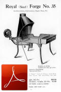 Canedy-Otto
Manufacturing Company catalogs. Here are two Canedy-Otto catalogs that can be
downloaded and viewed in Adobe Reader. These are PDF files. The first catalog
(near right) is the Catalog Number 8, and this catalog is complete. The catalog
number 8 shows everything available from Canedy-Otto at that time including;
forges and hoods, blowers, post drills, and floor model drills. The second catalog
is a partial copy of the Catalog Number 12 (at far right). The second catalog is
not complete - it is a partial series that shows only drills made by Canedy-Otto
at the time. The first half of both catalogs show the products that were available
from the company, and the second half of the catalogs lists parts for all of the
products in the catalog.
Canedy-Otto
Manufacturing Company catalogs. Here are two Canedy-Otto catalogs that can be
downloaded and viewed in Adobe Reader. These are PDF files. The first catalog
(near right) is the Catalog Number 8, and this catalog is complete. The catalog
number 8 shows everything available from Canedy-Otto at that time including;
forges and hoods, blowers, post drills, and floor model drills. The second catalog
is a partial copy of the Catalog Number 12 (at far right). The second catalog is
not complete - it is a partial series that shows only drills made by Canedy-Otto
at the time. The first half of both catalogs show the products that were available
from the company, and the second half of the catalogs lists parts for all of the
products in the catalog.
Latest update March 15, 2023.
Attention stupid! Working with old machinery is Not for amateurs! Due to the age of these drills, most parts are unavailable and must be made by a competent machinist. These drills are obsolete! Many of the original manufacturers have gone completely out of business or have changed ownership and no longer stock parts for the old drills. Buyer beware! You are on your own if you buy one of these old drills. There are no longer any parts made for these drills. If you break something, then you manufacture your own parts. If you have a problem with making your own parts then DON'T buy one of these drills. Are you an idiot? Are you a moron? Are you too stupid to understand this? I can't help you if you buy a broken drill. In fact I just don't care. If you buy one of these drills and it doesn't work and you aren't skilled enough to figure it out on your own, then don't bother me because I can't help you. These drills are for experts that can figure these things out on their own. Not for morons that buy broken tools and expect everyone else in the world to help them for free. If you have to ask me how to do it, then you haven't got what it takes to repair one of these old drills.
Original post October, 1999
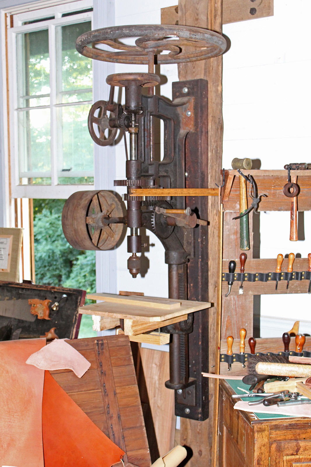

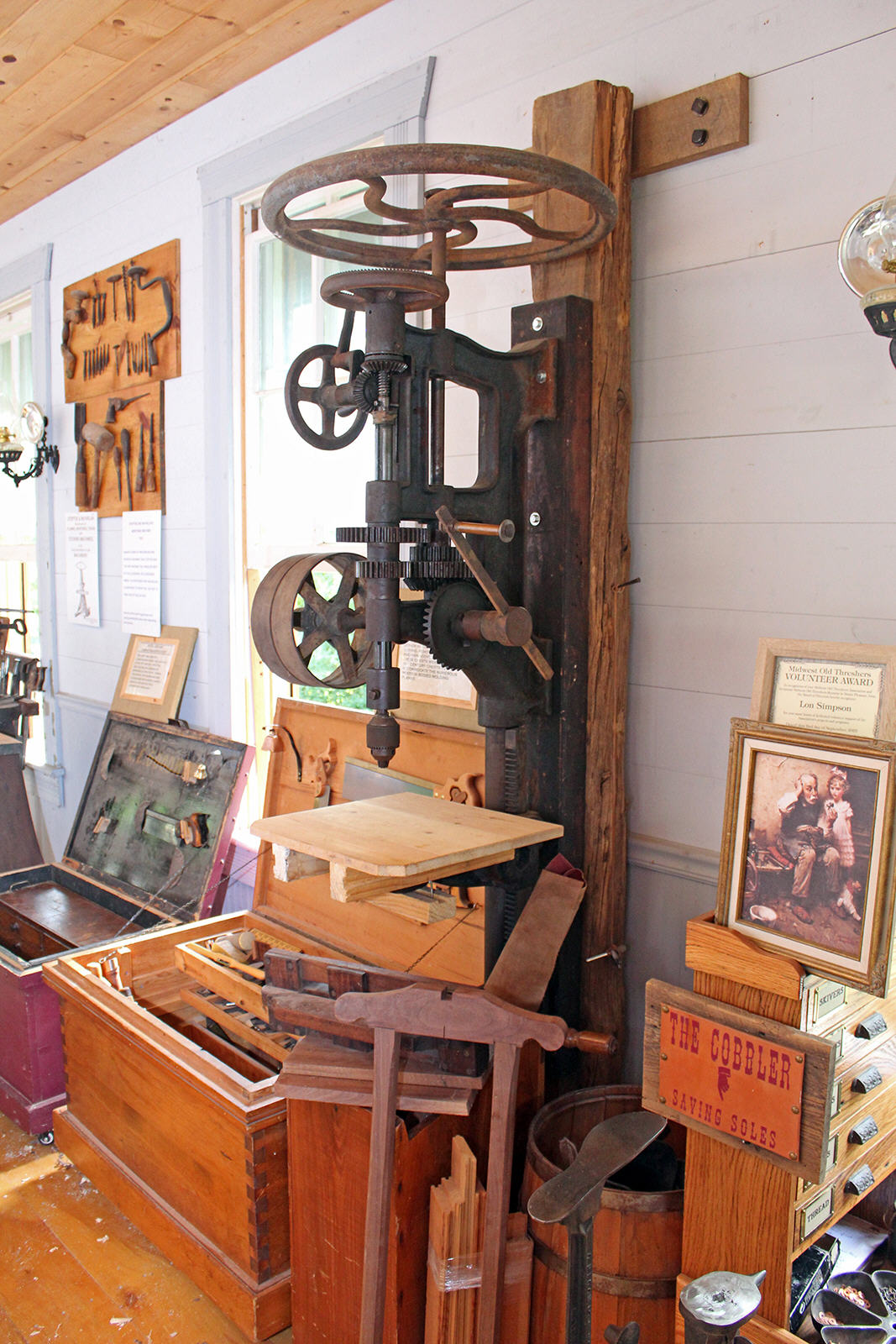
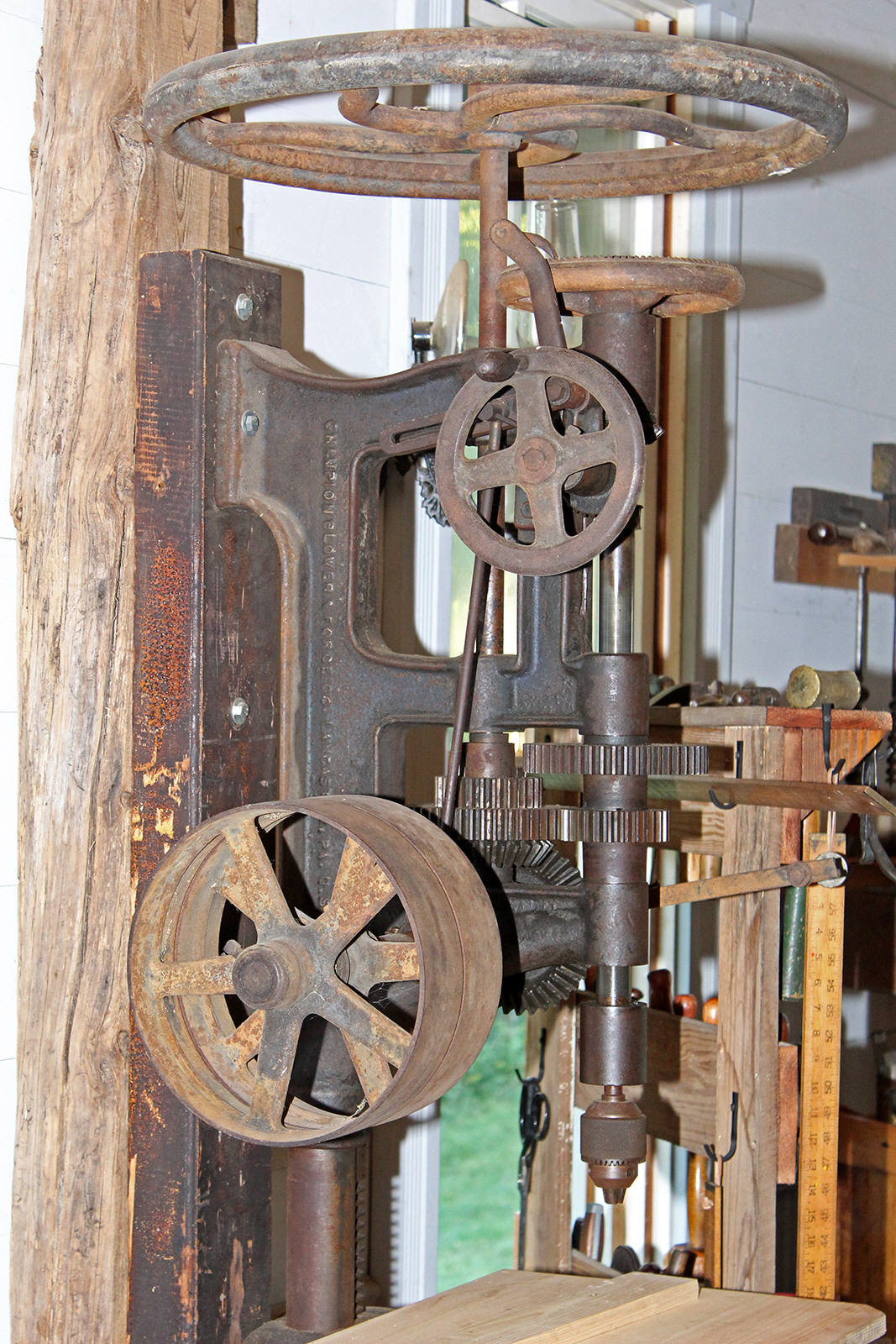
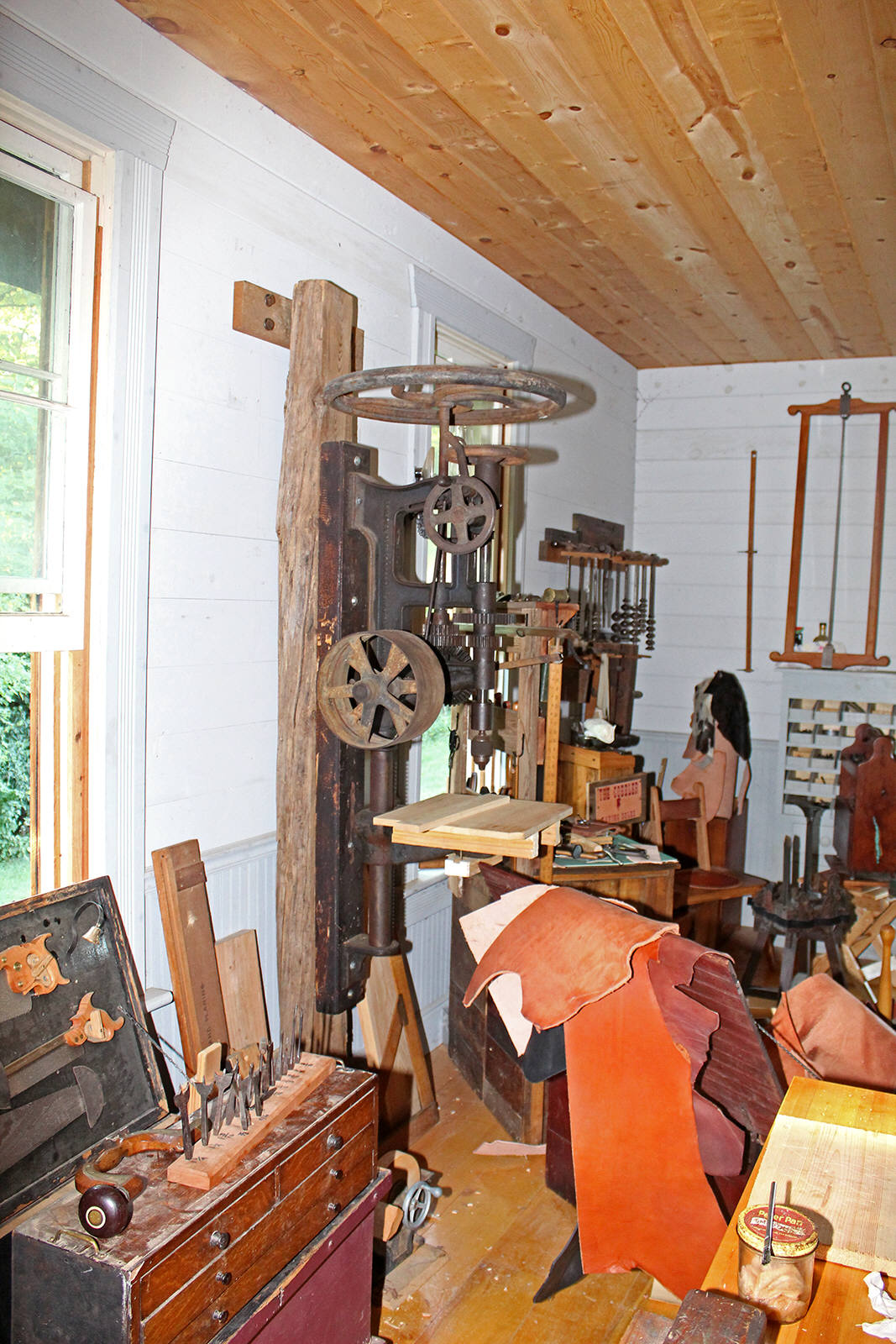